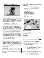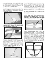
Remove the tape holding the ailerons in neutral. You can now test
the operation of the ailerons with your radio system. The ailerons
should move smoothly with transmitter stick movements and the
ailerons should be moving in the correct directions (right aileron
movement raises the right aileron and lowers the left aileron).
Recheck the centering of the ailerons using the APG tool. If some
adjustment is needed, use a pair of needle nose pliers to open or
close the "V"-bend in the pushrod. Finally, we suggest you put the
APG tool in your field box in case you need it again in the future.
With the exception of adding the decals, the wing is now complete
and ready to use.
MOUNTING THE TAIL GROUP:
❑
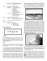
1) The elevators are now hinged to the horizontal stabilizer,
using the same hinging method as the ailerons. NOTE: The right
elevator half has two pre-drilled holes, near its inboard leading
edge, to accept the control horn. Make sure when hinging the
elevators to the stabilizer, it is with these holes on the right side.
❑
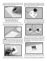
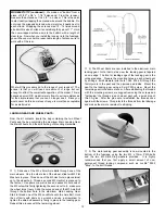
2) The horizontal stabilizer and elevator assembly is now
glued in place to the fuselage.
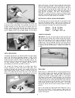
First mount the wing to the
fuselage with the provided 4-40 x 1" nylon wing-mounting bolt.
Trial fit the stabilizer in place into the slot at the rear of the
fuselage. Visually center the stabilizer in top view. Use a tape
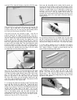
measure or ruler to measure the distance from the tip of the
aileron to the tip of the stabilizer and note the measurement. Take
the same measurement on the other side of the model - the two
measurements should be the same or within 1/16" or so of each
other. Also make sure the slot in the center of the stabilizer is
aligned directly beneath the vertical fin slot at the top rear of the
fuselage. Use the vertical fin to check that it fits in place without
leaning one way or the other.
Turn the wing over and use another piece of tape along the hinge
line to temporarily "lock" the aileron in this neutral position.
Repeat this process with the opposite aileron. When viewing the
wing from the side, the two ailerons should now be aligned with
each other and in the neutral position to the wing.
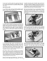
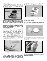
b) Attach the "Z"-bend end of the pushrod to the exposed servo
output arm, making sure the "V"-bend is facing away from the
wings surface. Attach opposite pushrod in the same manner. Slip
a plastic Pushrod Keeper onto each pushrod, with its arm facing
to the control horn, as shown.
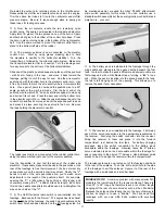
c) Hold the pushrod end against the control horn, at its
outermost hole location. Use a fine tipped marker to mark the
pushrod wire at the control horn hole location.
Remove the pushrod from the servo output arm and use a good
pair of pliers to now bend the wire to a 90
O
angle at the mark just
made. Trim the bent end of the wire to a length of 3/16" and
lightly sand off any burrs on the cut end. Reinstall the pushrod to
the servo output arm and press the bend end of the pushrod
through the control horn hole. Slide the Pushrod Keeper back to
the control horn and flex its arm over the wire end. Press the
keeper in place over the wire and against the control horn. Repeat
this process on the opposite aileron.
6
X
X = SAME DIMENSION
X


