background image

Lanier R/C


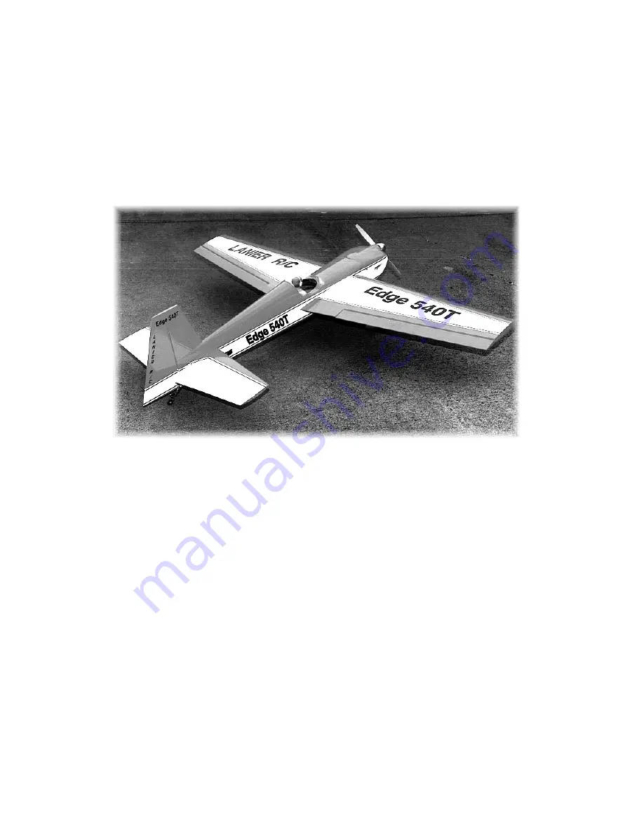
1.20 Edge 540T 

A

lmost

 R

eady to 

F

ly 


WARNING! THIS IS NOT A TOY! 

THIS IS NOT A BEGINNERS AIRPLANE


This R/C kit and the model you will build from it is not a toy!  It is capable of serious bodily harm and property 
damage.  It is your responsibility, and yours alone - 

to build this kit correctly, properly install all R/C components and 

flying gear (engine, tank, radio, pushrods, etc. and to test the model and fly it only with experienced, competent help, 
using commonsense and in accordance with all safety standards as set forth in the Academy of Model Aeronautics Safety 
Code.  It is suggested that you join the AMA and become properly insured before attempting to fly this model.  If you are 
just starting R/C modeling, consult your local hobby dealer or write to the Academy of Model Aeronautics to find an 
experienced instructor in your area.  Write to:  Academy of Model Aeronautics, 5151 Memorial Dr. Muncie, IN  47302 
 

LIMITED WARRANTY 

Lanier R/C is proud of the care and attention that goes into the manufacture of parts for its model kits.  The company 
warrants that for a period of 

3

0 days, it will replace, at the buyers request, any part or material shown to the company’s 

satisfaction to have been defective in workmanship or material at the time of purchase. 
No other warranty of any kind, expressed or implied, is made with respect to the merchandise sold by the company.  The 
buyer acknowledges and understands that he is purchasing only a component kit from which the buyer will himself 
construct a finished flying model airplane.  The company is neither the manufacturer of such a flying model airplane, nor a 
seller of it.  The buyer hereby assumes the risk and all liability for personal or property damage or injury arising out of the 
buyers use of the components or the finished flying model airplane, whenever any such damage or injury shall occur. 
Any action brought forth against the company, based on the breach of the contract of sale to the buyer, or on any alleged 
warranty thereunder, must be brought within one year of the date of such sale, or there after be barred.  This one-year 
limitation is imposed by agreement of the parties as permitted by the laws of the state of Georgia. 

© 2001 Lanier R/C 

Содержание MARINER 40 MK II ARF

Страница 1: ...acture of parts for its model kits The company warrants that for a period of 30 days it will replace at the buyers request any part or material shown to the company s satisfaction to have been defecti...

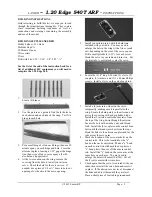
Страница 2: ...w depending on the size of the servo you use Drill a small pilot hole 1 32 for each screw Hook the servo to your radio and turn it on Set the trim tabs to neutral and center the servo 6 Locate the 2 8...

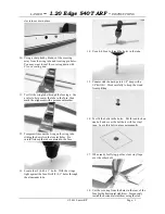
Страница 3: ...e centered in the fuse 13 Locate the 2 4 40 x 1 bolts With the wings tight against the fuse Drill 2 0 1 holes through the aluminum tube 14 Use a 4 40 tap to thread the holes in the tube 15 Counter sin...

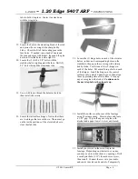
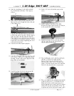
Страница 4: ...tube 23 Locate the 3 hinge holes in each of the elevator halves rudder and corresponding holes on the stabilizers then open the covering with a sharp hobby blade Test fit one of the 9 hinges in each...

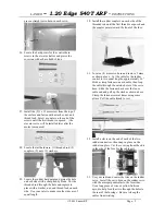
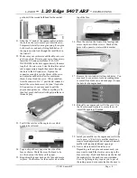
Страница 5: ...of the threaded rod until the first thread is exposed and the coupler points toward the front of the fuse 31 Locate a 4 arm servo horn and remove 2 arms as shown above Cut the cable for the rudder co...

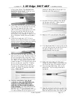
Страница 6: ...ertical stabilizer 38 Locate the springs for the tail and prepare the ends by bending a loop on each end 39 Drill a 1 16 hole in the rudder just past the clevis 40 Install a spring on each side of the...

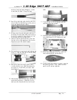
Страница 7: ...8 32 bolts and temporarily mount the engine on the firewall with 8 32 x 1 bolts Dubro 318 washers Dubro 327 and blind nuts Dubro 347 48 Measure the distance from the firewall to the front of the prop...

Страница 8: ...the engine to see what needs to be relieved 54 Tape a strip of heavy paper on the side of the fuse as shown Mark the areas that need to be cut then cut out the holes on the paper 55 Reposition the pap...

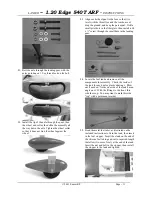
Страница 9: ...le on each arm You may need to enlarge the hole with a small drill bit Cut off the 3 extra arms with wire cutters Skip to step 77 64 Front servo installation Note For 3d aerobatics or when using a hig...

Страница 10: ...d bend one end down Slide the other piece of shrink tubing down the pushrod if needed 75 Insert the control rod in the pushrod and lay over the elevator servo Mark the intersection and make a z bend f...

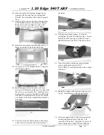
Страница 11: ...ll a 4 x screw through the small hole in the landing gear 84 Locate the fuel tank and remove all the components for assembly Check the inside of the tank for any dust or plastic shavings Blow out if n...

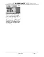
Страница 12: ...s in place then use screws to hold down the hatch The latter is recommended if you need to install your battery in the front compartment to balance your edge 91 Test fit your top fuse hatch in place t...

Страница 13: ...nt 4 to 4 3 4 back from the leading edge measured at the fuselage side 97 Move your battery for or aft as needed to achieve a balance If needed put the battery in the forward compartment behind the fi...

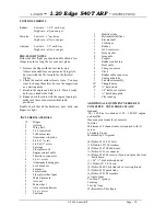
Страница 14: ...gine control cable 1 Throttle ez connector 8 4 x screw 1 Aluminum landing gear 2 4x20 mm bolt 2 4mm nut 4 4mm washer 2 Fiberglass wheel pant 2 Mail wheel axle 2 Axle nut 2 Main wheel 2 Axle collar and...

Отзывы: