LANIER
– 1.20 Edge 540T ARF -
INSTRUCTIONS
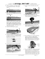
tube to hold it in place. Center it as was done
with the wing tube.
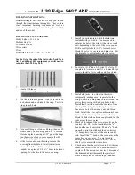
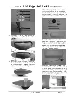
19. Locate the hole in the mounting block of the stab
and pierce the covering with a sharp hobby
blade. Check the fit of the locating pins in the
fuse holes. If needed, run a bead of ca around
the pins and spray with kicker, then sand the glue
down to fit in the holes with a tight fit.
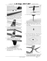
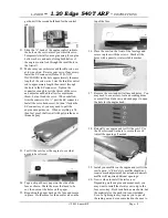
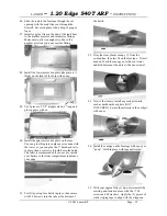
20. Locate the (2) 4-40 x 5/8” bolts with the
stabilizer halves tight against the fuse. Drill (2)
0.1” holes through the aluminum tube.
21. Use a 4-40 tap to thread the holes in the tube,
then install the screws.
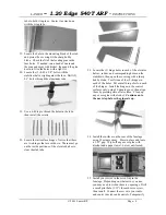
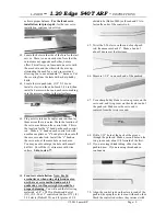
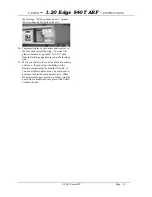
22. Locate the tail surface hinges. Notice that there
are two hinges that are cut down. These must go
on the inside positions of the elevator halves to
clear the stab tube.
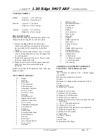
23. Locate the (3) hinge holes in each of the elevator
halves, rudder, and corresponding holes on the
stabilizers, then open the covering with a sharp
hobby blade. Test fit one of the (9) hinges in
each of the holes. Put a small drop of oil on each
of the hinges. Install the hinges in the control
surfaces only, using 30 minute epoxy, then align
them by pressing onto a flat surface. Clean up
any excess glue with alcohol.
Continue on to
the next step before the glue sets up.
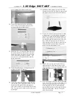
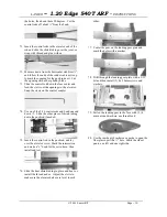
24. Install the surfaces on the rear of the fuselage
using 30 minute epoxy. Press in place and leave
a 1/32” gap. Wipe off any excess glue with
alcohol and a paper towel. Let set until cured.
25. Install your servos in the servo tray in the
fuselage. Depending on what servos you use,
you may need to widen the servo openings. Drill
a small pilot hole (1/32”) for each servo screw,
then install. Connect the servos to your radio
and center trim tabs and controls. Temporarily
© 2001 Lanier R/C
Page - 4


