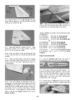
D 3 The doubler for rib W-3 is marked for a long,
narrow notch Extend the lines of this notch to the
edge of the doubler, and cut out this notch
LEADING & TRAILING EDGES
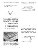
D 1 The shaped and notched wing leading edges
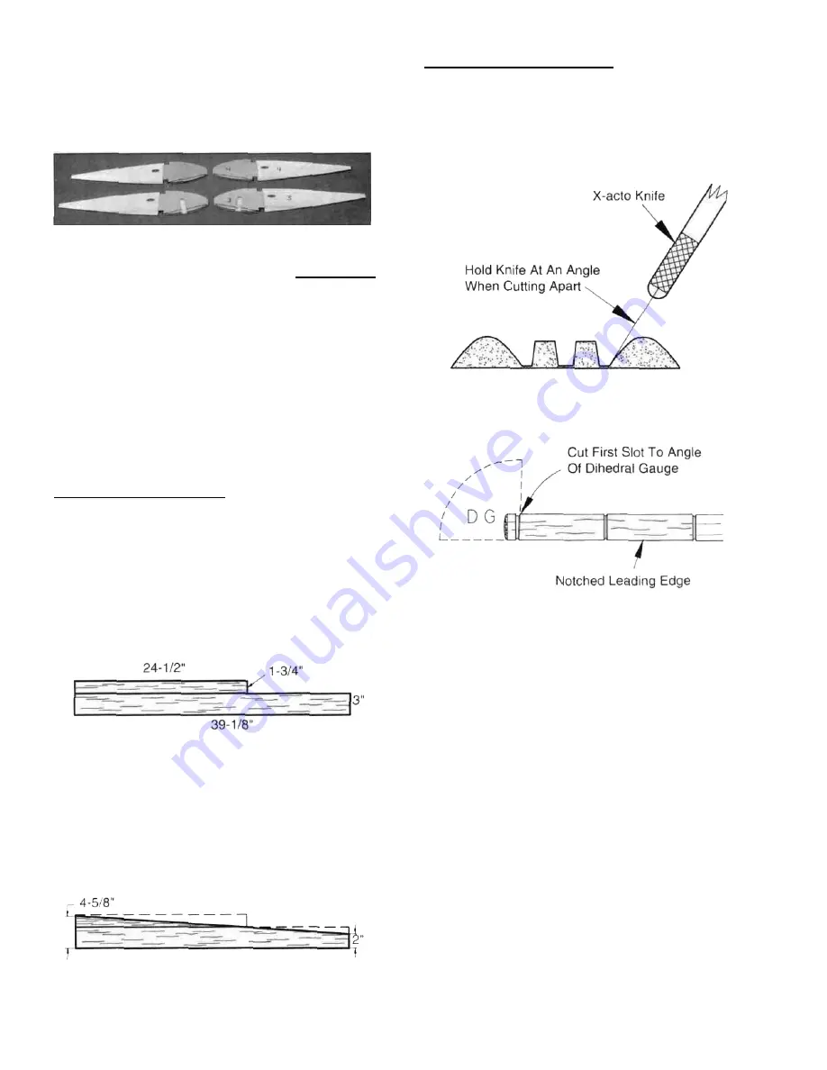
(LE) and trailing edges (TE) are fastened together by
thin strips of balsa Separate them by cutting with an
X-acto knife, as shown in the following sketch.
D 4 Glue these die-cut 1/8" ply landing gear doublers
to ribs W-3 and W-4 NOTE: Make a RIGHT and a
LEFT set, gluing the doublers to the inboard side
of the ribs. Take care to carefully align the doublers
with the spar notches The doublers are slightly
shorter than the ribs at the front edge, to allow fitting
the ribs into the leading edge notches
D 5 Cut out the long slot in the W-3 ribs using the
slot in the doublers as a guide
D 6 If you will be installing B&D retracts, drill a 3/8"
hole in the #4 doublers, using the punched hole in the
W-4 ribs as a guide.
LEADING EDGE SHEETING
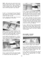
D 1. Prepare the leading edge sheeting as follows
Edge glue the 3/32" x 1-3/4" x 24-1/2" balsa sheets to
the 3/32" x 3" x 39-1/8" balsa sheets as shown here,
making four sets. NOTE: The two smaller front
sheets will be cut on a diagonal in the next step,
providing you with the front pieces you will need to
complete the 3rd and 4th sets
D 2. Now measure and mark the balsa sheeting (see
sketch below), then cut the angle in the sheeting,
cutting along a metal straightedge for accuracy
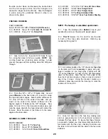
D 2 Examine the shaped, notched leading and
trailing edges Notice that the notches at one end of
each LE and TE are 3-1/2" apart These are the
notches for W-1 and W-2 Also notice that all notches
in the LE and TE are vertical, however, rib W-1 will be
installed at a slight angle using the Dihedral Gauge
Therefore, you should now modify the notch for W-1
by cutting it to the angle of the rib You may
determine the approximate angle of the cut by holding
the Dihedral Gauge (DG) against the LE as shown
above.
BUILD THE WING PANELS
NOTE: It will be helpful to build the wing on a piece
of "Celotex" or other semi-soft (and flat) surface, into
which you may easily stick pins to firmly hold down the
wing parts while building, to avoid warps
D 1 Tape the plan to your flat work surface, and
cover the wing drawing with waxed paper (so you
won't glue the wing to the plan') NOTE: If your work
14
Содержание Ultra-Sport 1000
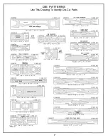
Страница 7: ...7 DIE PATTERNS Use This Drawing To Identify Die Cut Parts...
Страница 57: ...57...
Страница 59: ...2 View Drawing Use This For Planning Your Trim Scheme 59...

