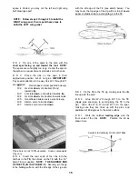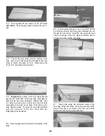
the stab anchor block, and between the anchor block
and the tail wedge (notice how the triangles are
sanded to a taper near the aft end). Glue the triangles
in place using the guidelines drawn in step 4, as
shown in the photo.
D (1) US10F21 1/4"x1/2"x2-11/32" Balsa Aft Cross Brace
D (1) US10F07 1/2"x30" Balsa Triangle Stock
D (1) US10F10 3/8"x15" Balsa Triangle Stock
D (1) US1 0F04 3/8" Ply Wing Hold-down Plate
D (1) US1 0F24 1/8"x3"x30" Balsa Fuse Bottom Sheeting
PREPARE FORMERS
PARTS NEEDED:
D (1) US10F16 1 /4" x 3/8" x 15" Balsa Stick (Stiffeners)
D (1) US10F28 Die-cut 1/8" Ply Formers F-2, F-4 and F-5
D (1) US10F29 Die-cut 1/8" Ply Former F-2A
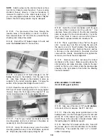
D 1. Glue F-2A to F-2, then drill 5/16" holes through
F-2, using the holes in F-2A as a guide. NOTE: Use
a scrap board as a backing when drilling, to help
prevent the plywood from splitting when the drill goes
through.
NOTE: The fuselage is assembled upside down.
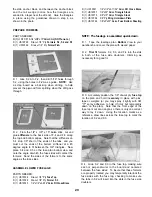
D 1. Tape the fuselage plan Bottom View to your
workbench and cover the plan with waxed paper.
D 2. Trial fit formers F-2, F-3, and F-4 into the slots
in both of the fuse side doublers, trimming as
necessary for a good fit.
D 3. Accurately position the 1/8" die-cut ply fuse top
on the plan and hold it securely in place with pins,
tape or weights (or you may spray it lightly with 3M
"77" spray adhesive, to hold it firmly but temporarily
down on the plan). Note that the front edge of the
fuse top is cut at an angle, so there is only one correct
way to lay it down. Using the location marks as a
reference, draw lines across the fuse top to mark the
location of F-2 and F-3.
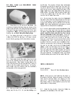
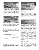
D 2. From the 1/4" x 3/8" x 15" balsa stick, cut and
glue stiffeners to the back side of F-4 and F-5 along
the top and bottom edges. Note that the stiffeners on
F-4 stop 1/8" short of the ends of the tabs, and you
must cut the ends of the bottom stiffener at a 45
degree angle to fit between the 3/8" triangles. Now
place F-4 and F-5 on the fuse plan bottom view and
note the angle at which the fuse sides will contact the
formers. Sand the sides of the formers to the same
angle as the fuse sides.
ASSEMBLE LOWER FUSELAGE
PARTS NEEDED:
D (1) US10F26 Die-cut 1/8" Ply Fuse Top
D (1) US10F29 Die-cut 1/8" Ply Former F-3
D (1) US10F20 1/4"x1/2"x3-9/16" Balsa Frt Cross Brace
D 4. Glue F-2 and F-3 to the fuse top, making sure
each is perpendicular to the board and centered
between the fuse sides. To insure that these formers
are properly located you may temporarily interlock the
fuse sides with the fuse top, checking to make sure
the tabs in F-2 will insert into the slots in the fuse side
doublers.
29
Содержание Ultra-Sport 1000
Страница 7: ...7 DIE PATTERNS Use This Drawing To Identify Die Cut Parts...
Страница 57: ...57...
Страница 59: ...2 View Drawing Use This For Planning Your Trim Scheme 59...

