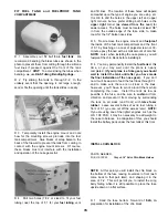
D 9 Carefully align the fin on the stab The fin must
be positioned perpendicular to the stab and must
line up with the fuselage centerline EXACTLY!
Securely glue the fin in place with epoxy, double-
checking alignment while the glue sets
INSTALL SERVOS, HORNS AND PUSHRODS
D 1. Re-mount the aileron servos in the wing, and
mount the nylon aileron horns.
D 2. Screw the steel clevises (METAL013)
approximately 2/3 of the way onto the threaded end of
the two 12" steel wire pushrods (WIRES16).
Steel Clevis Lock Clip
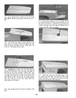
D 10. Trial fit the fin fairings into place along both
sides of the fin, carving them out to clear the washer.
Now securely glue them in place.
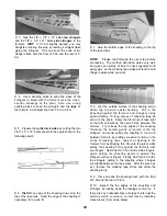
D 11 From the 1/2" balsa triangle supplied, cut and
securely glue fillets under the stab, at the stab/fuse
joint Note that the front ends of the triangles are
sanded to a taper before gluing them in place
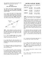
D 12 Temporarily attach the elevators and rudder to
check their fit and operation Cut the bottom rudder
hinge slot in the aft end of the fuse, and (if you are
building a taildragger) cut the slot in the fuse for the
tailgear bearing at the location shown on the fuse plan
side view.
D 3. Attach the clevises to the aileron horns, and
then, with the ailerons in the neutral position, mark the
pushrod wires where they cross the holes in the servo
arms Remove the pushrods and make a "Z-bend" in
each rod at that point, using a "Z-bend pliers" or a
standard pliers Cut off the excess pushrod wire.
D 4. Remove the servo wheel from the servo and
work the Z-bends into the wheel (NOTE: You may
have to enlarge the servo wheel holes with a 5/64"
diameter drill bit) Replace the servo wheel and check
the operation of the ailerons (See page 47 for the
recommended amount of aileron movement).
REMEMBER: Plan your servo installation carefully,
as your setup may differ from the plans and photos,
depending on which engine you use, and whether you
are building a trike or taildragger.
D 5. Re-mount the elevator, rudder and throttle
servos in the fuselage.
D 13. Glue the 3/8" balsa dorsal fin in place on the
turtle deck The dorsal fin, like the fin, must also line
up with the fuselage centerline Sand the leading
edge of the dorsal fin to a rounded shape, and blend it
to the fin with balsa filler.
D 14. Temporarily install the rudder, and observe
how the bottom of the rudder lines up with the bottom
of the fuse Sand the bottom of the rudder to match
the bottom of the fuse.
D 6 Hold the large nylon control horns (NYLON02)
on the elevator and rudder in the positions shown on
the plan and mark the mounting hole locations Drill
3/32" holes at these locations
D 7. Harden the balsa in the area of the control
horns (on both sides of the control surfaces) by
poking several holes with a pin, then applying thin
CA glue Sand smooth.
46
Содержание Ultra-Sport 1000
Страница 7: ...7 DIE PATTERNS Use This Drawing To Identify Die Cut Parts...
Страница 57: ...57...
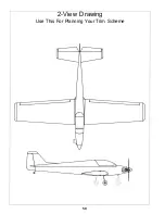
Страница 59: ...2 View Drawing Use This For Planning Your Trim Scheme 59...


