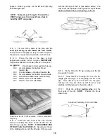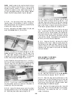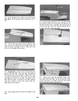
D 5. Permanently attach the nose gear bearings (if
applicable) to the back of the firewall with the 4-40 x
3/4" machine screws, cut off the excess bolt length
that protrudes through the firewall, and trial fit the nose
gear strut and steering arm. Temporarily mount your
engine mount and engine onto the firewall, making
sure everything fits properly. Remove the engine
mount and the nose gear, leaving the nylon nose gear
bearings in place. Now glue the rubber expansion
nuts into the holes, per the instructions that came with
the mount.
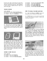
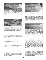
D 3. Temporarily assemble the stab base, the stab
anchor block and the die-cut 1/8" ply former F-6 onto
one of the fuse sides. F-6 should be all the way aft in
the slot in the stab base. While holding these parts
together, draw lines on the bottom of the stab base to
mark the location of the anchor block, F-6 and the
inside edge of the fuse doubler. Now assemble these
parts on the other fuse side and mark the inside edge
of the fuse doubler along the other edge of the stab
base. Now disassemble the parts.
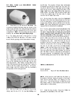
D 4. Glue the die-cut 1/8" ply F-6 into the slot in the
stab base. F-6 must be installed in the slot as far aft
as it will go, and it must be perpendicular to the stab
base. Also glue the stab anchor block to the stab
base, using the guidelines drawn in the previous step
for positioning.
PREPARE STAB BASE
PARTS NEEDED:
D (1) US10F30 Die-cut 1/8" Ply Stab Base
D (1) US10W35 Die-cut 1/8" Ply Stab Anchor Plates
D (1)
US10F29
Die-cut 1/8" Ply F-6
D (1) US10F42 1/4" x 30" Balsa Triangle Stock
D 1. Find the two die-cut 1/8" birch ply stab anchor
plates, and glue them together to make a 1/4" block.
Trial fit this block into the slots in the aft fuse side
doublers, sanding the edges of the block until it fits.
Also check the thickness of the block and sand it
down as necessary so it does not prevent the stab
base from fully seating into the slots in the doublers.
D 2. Trial fit the die-cut 1/8" ply stab base into the
slots in the aft fuse side doublers. Sand the aft end of
the stab base for a good fit against the tail wedge.
D 5. From the 1/4" balsa triangle stock, cut pieces
to fit on both sides of the stab base between F-6 and
28
Содержание Ultra-Sport 1000
Страница 7: ...7 DIE PATTERNS Use This Drawing To Identify Die Cut Parts...
Страница 57: ...57...
Страница 59: ...2 View Drawing Use This For Planning Your Trim Scheme 59...


