NOTE: Install a wheel on the strut and check out how
much force it takes to raise the wheel If you are using
standard (heavy) wheels, it may be necessary to
increase the tension on the retract assist spring If
you are using lighter wheels, such as Sullivan "Skylite"
wheels, the stock spring tension may be adequate
D D 23. You previously drew lines through the
location holes in the doublers on ribs W-3 and W-4.
Now measure down 1/4" from this line (toward the top
sheeting) and make a few marks
D D 24 Find all the 1/4" balsa triangle in the kit, and
select the hardest balsa for the next step
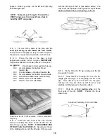
D D 29 Install the retract mechanism (with the gear
strut but without a wheel) and the pushrod * Cut
clearance holes and notches in the ribs and mounting
plate as required for the strut and pushrod Cycle the
gear a few times to make sure everything clears
*Pushrods for optional retracts not included in kit
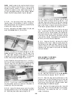
D D 30 This is a good time to file a "flat" on the gear
strut A good way to do this is to align the axle with
the spar (or set it to "toe-in" slightly), then tighten the
set screw to mark the strut Remove the strut, and file
a flat area on the strut similar to the stock strut that
came with the retracts Re-install the strut, tighten the
set screw, and check the strut alignment.
D D 31. Remove the strut, but leave the retract
mechanism in the mount Measure exactly where the
strut socket is, and make reference marks on the spar
and LE so that you can later cut into the leading edge
sheeting in the right place to find it after the sheeting
has been installed
D D 25. Cut pieces of 1/4" balsa triangle to run 1/4"
below the lines on the doublers, from the spar to the
LE Glue these triangles to the doublers to serve as
supports for the retract mounting plates Cut away the
section of the triangle that bridges the slot in W-3.
D D 26 Bevel the rear edge of the 1 /4" x 1 -5/16" x 3-
5/16" ply aft retract mounting plate to fit snugly against
the spar Bevel the front edge of the tapered 1/4 ply
retract mounting plate to fit snugly against the LE
D D 27 Trial fit your retract mechanism onto the
mounting plates, and cut out notches in the plates as
necessary to clear the mechanism
D D 28 Using 30-minute epoxy, glue the retract
mounting plates securely to the rib doublers, spar and
LE Wipe away any excess epoxy along the LE
WING ASSEMBLY CONTINUES
(for all landing gear options)
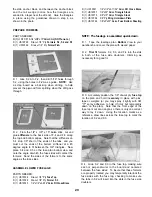
D D 32 Glue one of the die-cut 1/8" ply LE doublers
to the back of the LE, between ribs W-1 and W-2
D D 33 Place the wing panel upside down on the
building board, turn the TE support jig end for end and
pin the TE to the support jig (again, with the narrow
end of the jig at the wing tip), and place blocks under
the leading edge for additional support
D D 34 Sand the TE to blend with the ribs Sand off
any excess glue or other imperfections on the bottom
of the wing Then install the 3/32" x 2" x 39-3/8"
bottom TE sheeting.
18
Содержание Ultra-Sport 1000
Страница 7: ...7 DIE PATTERNS Use This Drawing To Identify Die Cut Parts...
Страница 57: ...57...
Страница 59: ...2 View Drawing Use This For Planning Your Trim Scheme 59...


