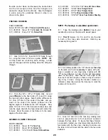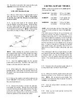
D 11 Using a long T-bar or sanding block with 80-grit
sandpaper, sand the sheeting and stringers flush with
the top edges of the formers.
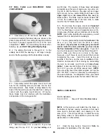
D 12. Glue the 5/8" x 2-7/8" x 31" balsa turtle deck
top block to the tops of the formers, stringers and
sheeting Then trim the ends of the top block flush and
on the same angle as F-3A and F-6A.
HINT: In the next step it will be helpful in keeping the
top block symmetrical if you first mark a fuselage
centerline on the top of the top block from front to
back (this is a line from the centerline of F-3A to the
centerline of F-6A).
NOTE: From now on, when working on the fuselage
upside down, you should always support the fuselage
in a protective stand, such as a Robart "Super Stand"
to avoid dents and nicks.
ASSEMBLE THE NOSE SECTION
PARTS NEEDED
D (2) US10F17 1/4" x 5/16" x 11" Balsa Cockpit Sides
D (1) US10F34 Die-cut 1/16" Ply Spinner Ring
D (2) US10F23 Shaped 3/4" Balsa Top Front Block
Halves
D (1) US1 0W26 Die-cut 3/32" Balsa Instrument Panel
D (1) US10F03 1/2" x 3" x 24" Balsa Cowl Side Stock
D (1) US10F06 1/2" x 18 Soft Balsa Triangle Stock
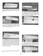
D 1 Find the 1/4" x 5/16" x 11" balsa cockpit sides.
Cut off one end of each stick at an angle to fit the front
edge of the backrest (F-3A). The cockpit sides are
5/16" tall and 1/4" wide.
D 2. Glue the cockpit sides to the top edge of the
fuse sides and to F-3A The outside edge of the
cockpit sides should be flush with the outside edge of
the fuse sides
D 13 Carve and sand the top block to blend
smoothly with the sheeting (see the cross-sections on
the plan) HINT: Use a razor plane (or a sharp wood
chisel) and a sanding block with new 50 or 80-grit
sandpaper for rough shaping the top block.
HINT: For a super-smooth and uniform finish on your
turtle deck, cut a 2-1/4" x 11" strip of 320 or 400-grit
wet-or-dry sandpaper, and work it like a "shoe-shine
cloth" across the top of the turtle deck.
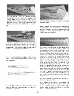
D 3 Measure, mark and sand off the cockpit sides
according to the sketch Then sand the top front
corners of the fuse sides on the same angle, to blend
with the cockpit sides.
D 4. Attach the engine mount to F-1, and attach the
engine to the mount.
D 5. From a scrap of 3/32" balsa, cut four small
pieces and tack glue them to the 1/16" ply spinner
ring as shown, using a very small amount of thick CA
(these will be removed later) Make sure the
backplate and ring are properly aligned.
40
Содержание Ultra-Sport 1000
Страница 7: ...7 DIE PATTERNS Use This Drawing To Identify Die Cut Parts...
Страница 57: ...57...
Страница 59: ...2 View Drawing Use This For Planning Your Trim Scheme 59...


