Setup & Operation 12. Option Units
RC180 Rev.17
87
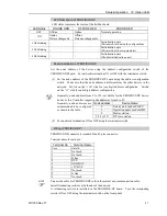
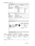
LED Description of PROFIBUS-DP
LED status represents the status of the fieldbus board.
LED status
ONLINE GRN
OFFLINE RED
ERROR RED
OFF
Offline
Online
Normal operation
ON
Online
Data exchangeable
Offline
Data unexchangeable
−
1 Hz blinking
−
−
Initialization error
(Mismatch with network configuration)
2 Hz blinking
−
−
Initialization error
(Mismatch with user parameter)
4 Hz blinking
−
−
Initialization error
(Module initialization error)
Board Installation of PROFIBUS-DP
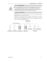
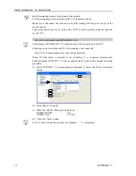
Set the node address of the device using the address configuration switch of the
PROFIBUS-DP board. Set network termination ON or OFF with the terminator switch.
(1)
Set the node address of the PROFIBUS-DP board using the address configuration
switch. Make sure that the node address is different from the other devices in the
network. Switch on the “
×
10” side for tens digit address configuration. Switch
on the “
×
1” side for units digit address configuration.
Generally, a node address from 0 to 125 is available for the PROFIBUS-DP device,
however, this Controller supports node addresses from 0 to 99.
Generally, node addresses are
recommended to be configured
as shown in the table.
Node address
Device Name
0
Service unit such as PG/PC
1
Operation panel such as HMI
2
Master station
3-99 (-125)
DP slave station
(2)
Turn network termination ON or OFF using the terminator switch.
Wiring (PROFIBUS-DP)
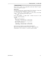
PROFIBUS-DP connector is standard D-sub 9 pins connector.
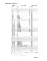
Terminal name for each pin
Terminal No
Terminal Name
Case
Shield
1
Not used
2
Not used
3
B line
4
RTS
5
GND BUS
6
+5V BUS
7
Not used
8
A line
9
Not used
Prepare the cable for PROFIBUS-DP sold in the market as a communication cable.
Install terminating resistors at both ends of the network.
A terminating resistor is installed in the PROFIBUS-DP board. Turn the terminating
resistor ON or OFF using the terminator switch on the front panel.
NOTE
NOTE
Содержание RC180
Страница 1: ...Rev 17 EM164C3205F ROBOT CONTROLLER RC180 ...
Страница 2: ...ROBOT CONTROLLER RC180 Rev 17 ...
Страница 13: ...Safety This section contains information for safety of the Robot System ...
Страница 14: ......
Страница 19: ...Setup Operation This section contains information for setup and operation of the Robot Controller ...
Страница 20: ......
Страница 124: ...Setup Operation 12 Option Units 112 RC180 Rev 17 ...
Страница 125: ...Maintenance This section contains maintenance procedures for the Robot Controller ...
Страница 126: ...114 ...

