background image

Maintenance  8. Trouble Shooting 


RC180 Rev.17 

245 

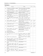
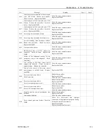
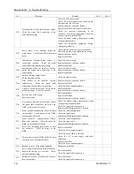
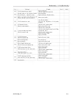
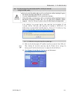
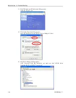
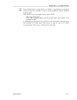
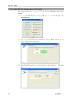
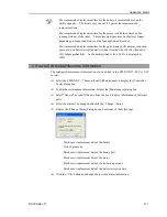
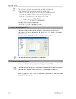
When  “EPSON Robot Controller RC170 (or RC180)”  is registered and located under 

“Universal Serial Bus controllers”  in step (5), the development PC and the Controller 

connect properly. 

If the following error message appears, please contact EPSON. 

“Cannot connect to controller. 
!! Error: 1805, Connection failure, check the controller startup and connection of the 
communication cable.”   

If “EPSON Robot Controller RC170 (or RC180)”  is not located under  “Universal Serial 

Bus controllers”  but located under “Other devices”  in step (5), refer to 

8.2.2 When 

recognized under “Other devices” in Windows Device Manager

.


NOTE


Содержание RC180

Страница 1: ...Rev 17 EM164C3205F ROBOT CONTROLLER RC180 ...

Страница 2: ...ROBOT CONTROLLER RC180 Rev 17 ...

Страница 3: ...RC180 Rev 17 i ROBOT CONTROLLER RC180 Rev 17 Copyright 2006 2016 SEIKO EPSON CORPORATION All rights reserved ...

Страница 4: ... warranty period information However customers will be charged for repairs in the following cases even if they occur during the warranty period 1 Damage or malfunction caused by improper use which is not described in the manual or careless use 2 Malfunctions caused by customers unauthorized disassembly 3 Damage due to improper adjustments or unauthorized repair attempts 4 Damage caused by natural ...

Страница 5: ... Operating system Microsoft Windows 7 Operating system Microsoft Windows 8 Operating system Throughout this manual Windows XP Windows Vista Windows 7 and Windows 8 refer to above respective operating systems In some cases Windows refers generically to Windows XP Windows Vista Windows 7 and Windows 8 NOTICE No part of this manual may be copied or reproduced without authorization The contents of thi...

Страница 6: ...ts assumes the use in the local network such as the factory LAN network Do not connect to the external network such as Internet In addition please take security measure such as for the virus from the network connection by installing the antivirus software Security support for the USB memory Make sure the USB memory is not infected with virus when connecting to the Controller Every data of the Cont...

Страница 7: ... 3 2 Particular Status Display 18 2 4 Safety Features 18 3 Installation 21 3 1 Unpacking 21 3 2 Environmental Requirements 21 3 2 1 Environment 21 3 2 2 Installation 22 3 2 3 Install inside the Cabinet 24 3 3 Power Supply 25 3 3 1 Specifications 25 3 3 2 AC Power Cable 26 3 4 Cable Connection 26 3 4 1 Typical Cable Connection 27 3 4 2 Connecting Manipulator to Controller 30 3 5 Noise Countermeasur...

Страница 8: ...ons 40 6 2 2 Adoptable USB Memory 40 6 3 Controller Status Storage Function 41 6 3 1 Controller Status Storage with Trigger Button 41 6 3 2 Controller Status Storage with Teach Pendant Option 41 6 3 3 Load Data with EPSON RC 5 0 42 6 3 4 Transfer with E mail 43 6 4 Details of Data 44 7 LAN Ethernet Communication Port 45 7 1 About LAN Ethernet Communication Port 45 7 2 IP Address 46 7 3 Changing Co...

Страница 9: ... Remote Set Up 64 11 1 I O Signal Description 65 11 1 1 Remote Input Signals 65 11 1 2 Remote Output Signals 68 11 2 Timing Specifications 70 11 2 1 Design Notes for Remote Input Signals 70 11 2 2 Timing Diagram for Operation Execution Sequence 70 11 2 3 Timing Diagram for Program Execution Sequence 70 11 2 4 Timing Diagram for Safety Door Input Sequence 71 11 2 5 Timing Diagram for Emergency Stop...

Страница 10: ...232C 111 Maintenance 1 Safety Precautions on Maintenance 115 1 1 Safety Precautions 115 1 2 Lockout Tagout 116 2 Regular Maintenance Inspection 117 2 1 Schedule for Maintenance Inspection 117 2 2 Inspection Point 118 2 2 1 Inspection While the Controller is Turned OFF 118 2 2 2 Inspection While the Controller is Turned ON 118 3 Controller Structure 119 3 1 Location of Parts 119 3 2 Diagram of Cabl...

Страница 11: ...t 145 6 2 Battery 146 6 3 Motor Driver 148 6 3 1 Part Names 148 6 3 2 Replacing Motor Driver Axis from 1 to 4 148 6 3 3 Replacing Motor Driver Axis 5 and 6 153 6 4 CPU Board Unit 155 6 5 CF Compact Flash 158 6 6 Fuse 159 6 7 Option Unit 161 6 7 1 Remove Option Unit 1 161 6 7 2 Mount Option Unit 1 162 6 7 3 Remove Option Unit 2 162 6 7 4 Mount Option Unit 2 164 6 7 5 Remove Option Unit 1 2 165 6 7 ...

Страница 12: ...Table of Contents x RC180 Rev 17 8 2 2 When recognized under Other devices in Windows Device Manager 246 9 Maintenance Parts List 247 Appendix Alarm 248 ...

Страница 13: ...Safety This section contains information for safety of the Robot System ...

Страница 14: ......

Страница 15: ...quirements 2 Conventions Important safety considerations are indicated throughout the manual by the following symbols Be sure to read the descriptions shown with each symbol WARNING This symbol indicates that a danger of possible serious injury or death exists if the associated instructions are not followed properly WARNING This symbol indicates that a danger of possible harm to people caused by e...

Страница 16: ...als This product has been designed and manufactured strictly for use in a normal indoor environment Using the product in an environment that exceeds the specified environmental conditions may not only shorten the life cycle of the product but may also cause serious safety problems The robot system must be used within the installation requirements described in the manuals Using the robot system out...

Страница 17: ...ne by qualified personnel When connecting the plug be sure to connect the earth wire of the AC power cable colored green yellow on the Controller to the earth terminal of the factory power supply The equipment must be grounded properly at all times to avoid the risk of electric shock Always use a power plug and receptacle Never connect the Controller directly to the factory power supply Field wiri...

Страница 18: ...switch is disabled Example Tape is put around the switch to hold it closed Operating the robot system when the switch is not functioning properly is extremely hazardous and may cause serious safety problems as the Safety Door input cannot fulfill its intended function WARNING Do not open the cover s of the Controller except while maintaining it Opening the cover s of the Controller is extremely ha...

Страница 19: ...Setup Operation This section contains information for setup and operation of the Robot Controller ...

Страница 20: ......

Страница 21: ... USB2 0 or Ethernet TP1 Standard I O Remote I O Ethernet OP1 Standard Installation Requires preparation by uses CV1 Ethernet S5 series PLC Sequencer C3 series 1 EPSON RC 5 0 supports the following OS Windows XP Professional Service Pack 3 EPSON RC 5 0 Ver 5 2 0 SP3 or after is required Windows Vista Business Service Pack 2 EPSON RC 5 0 Ver 5 3 1 or after is required Windows 7 Professional EPSON RC...

Страница 22: ...rogrammable Actual value to be manually entered Positioning control PTP Point To Point control CP Continuous Path control Memory capacity Maximum Object Size 4 MB Point data area 1000 points per file Backup variable area Max 100 kB Includes the memory area for the management table Approx 1000 variables Depends on the size of array variables Teaching method Remote Direct MDI Manual Data Input Exter...

Страница 23: ...ature error detection Fan error detection Power Source 200 VAC to 240 VAC Single phase 50 60 Hz Maximum Power Consumption 2 5 kVA Depending on the Manipulator model Insulation Resistance 100 MΩ or more Rated Ambient Temperature 5 to 40 deg C Rated Relative Humidity 20 to 80 with no condensation Weight 1 For SCARA robot 2 9 0 kg Base unit without option For Six axis robot 3 10 5 kg Base unit ProSix...

Страница 24: ...ensions Dimension of RC180 UL is the same as RC180 Base Unit Four axis robot construction 130 5 275 302 170 5 5 Base Unit ProSix Driver Unit Six axis robot construction 376 130 75 5 130 5 275 170 5 RC180 Base Unit Option Unit 130 55 136 7 130 5 275 411 170 5 5 110 ...

Страница 25: ...unctions RC180 Rev 17 13 2 Part Names and Functions 2 1 Part Names RC180 2 3 7 9 10 12 1 13 14 17 18 19 20 21 22 23 24 1 1 11 12 2 16 15 1 2 1 2 6 4 5 8 RC180 UL 2 3 7 9 10 12 1 17 18 19 20 21 22 23 24 1 1 11 12 2 16 15 1 2 1 2 6 4 5 8 ...

Страница 26: ...n 2 3 LED and Seven segment LED 3 Seven segment LED Four digit seven segment LED displays the line number and the status of the controller error number warning number status of Emergency Stop and Safety Door For details refer to Setup Operation 2 3 LED and Seven segment LED 4 Signature label top panel The serial number of the Controller and other information are shown 5 MT label top panel The labe...

Страница 27: ...t cover using other screws may result in cable being stuck and or malfunction of the Controller 13 POWER switch Turns ON or OFF the Controller This is not available for RC180 UL For details refer to the Setup Operation 3 3 2 AC Power Cable For RC180 UL 14 Power Switch metal hasp To lock the power switch in the OFF position set the power switch to the OFF position and mount the metal hasp Lock the ...

Страница 28: ...6 Memory Port 21 TP OP port Connects Teach Pendant TP1 Option TP2 Option Operator Panel OP1 Option and TP OP bypass plug For details refer to Setup Operation 8 TP OP Port Do not connect the following to the TP OP port of RC180 Connecting to the followings may result in malfunction of the device since the pin assignments are different OPTIONAL DEVICE dummy plug Operation Pendant OP500 Operator Pend...

Страница 29: ...oller statuses occurred at one time the status indicated earlier on the following table is displayed For an example when both Emergency Stop and Safeguard statuses occurred at one time is displayed Controller status Display of seven segment Execute Controller status storage function to the USB memory Displays and repeatedly Complete Controller status storage to USB memory Displays for 2s Failure o...

Страница 30: ...fety features the Emergency Stop Switch and Safety Door Input are particularly important Make sure that these and other features function properly before operating the robot system For details refer to the Setup Operation 9 EMERGENCY Emergency Stop Switch The EMERGENCY connector on the Controller has expansion Emergency Stop input terminals used for connecting the Emergency Stop switches Pressing ...

Страница 31: ...hen the system detects that the load on the motor has exceeded its capacity Irregular Motor Torque out of control manipulator Detection The dynamic brake circuit is activated when irregularity with motor torque motor output is detected in which case the Manipulator is out of control Motor Speed Error Detection The dynamic brake circuit is activated when the system detects that the motor is running...

Страница 32: ...mic brake circuit is activated when relay deposition or junction error is detected Over Voltage Detection The dynamic brake circuit is activated when the voltage of the Controller is above the normal limit AC Power Supply Voltage Drop Detection The dynamic brake circuit is activated when the drop of the power supply voltage is detected Temperature Anomaly Detection The temperature anomaly is detec...

Страница 33: ...quate ventilation and cooling Install Controller in a location that allows easy connection disconnection of cables Item Condition Ambient temperature 5 to 40 deg C with minimal variation Ambient relative humidity 20 to 80 with no condensation First transient burst noise 2 kV or less Power supply wire 1 kV or les Signal wire Electrostatic noise 4 kV or less Base table Use a base table that is at le...

Страница 34: ...wn from A to D A B Fixture L Base Table Fixture L C D Base Table Fixture S Rack Base Table Fixture L There are two types of fixtures Mount the fixture to the Controller with the four attached screws Fixture L Used in A B and D Fixture S Used in I The length from the edge of fixture L differs by the side Refer to the following figure and mount the side with shorter distance from the edge to the scr...

Страница 35: ...k with screws and nuts 24 7 20 5 60 0 Front Side 20 5 60 0 Front Side When mounting direction is C Fixture S 59 8 59 8 Controller Only Controller ProSix Driver Unit No Option Unit 1 323 mm 4 398 mm Option Unit 1 2 378 mm 5 453 mm Option Unit 2 3 433 mm 6 508 mm Ensure the draft around the in out and also install the Controller by keeping the distance as follows to prevent the nose influence from o...

Страница 36: ...sfy the condition indicated in 3 2 1 Environment 3 2 2 Installation and also the following conditions The distance from the mounting surface and the inside of the door must be 220 mm or more 190 mm when using the option I O connector 220 mm or more Mounting Surface Controller I O Connector Option Product No R12B040710 When using the I O connector option 190 mm or more Set the temperature inside th...

Страница 37: ... 1 4 kVA Refer to Manipulator manual for Manipulator rated consumption Peak Current When power is turned ON approximately 150 A 2 ms When motor is ON approximately 60 A 5 ms Leakage Current Max 10 mA Ground Resistance 100 Ω or less Install an earth leakage circuit breaker or a circuit breaker in the AC power cable line at 15 A or less rated electric current Both should be a two pole disconnect typ...

Страница 38: ...y the users To Controller M4 Ring solderless terminal RC180 UL M5 Ring solderless terminal The AC plug in not attached to the AC power cable delivered at shipment Refer to the wire connection specification and attach a proper plug to the cable that is suitable for the factory power supply A plug is prepared as option Cable Wire Connection Specification Purpose Color AC power wire 2 cables Black Gr...

Страница 39: ...rial number of the Manipulator that should be connected is indicated on the Connection Check Label on the Controller Connect the Controller and the Manipulator correctly Improper connection between the Controller and the Manipulator may cause not only improper function of the robot system but also safety problems Before connecting the connector make sure that the pins are not bent Connecting with ...

Страница 40: ...r on the Manipulator and the M C SIGNAL connector on the Controller 4 EMERGENCY The EMERGENCY connector has inputs to connect the Emergency Stop switch and the Safety Door switch For safety reasons connect proper switches for these input devices For details refer to the Setup Operation 9 EMERGENCY 5 PC for development Connect the PC for development For details refer to the Setup Operation 5 Develo...

Страница 41: ...ach Pendant There are two types of connector shapes for the Teach Pendant TP cable A Circular connector TP cable B D sub 25pin For details refer to the Setup Operation 8 TP OP Port 10 OP cable Connect the option Operator Panel For details refer to the Setup Operation 8 TP OP Port ...

Страница 42: ...ntroller Connect the Controller and the Manipulator correctly Improper connection between the Controller and the Manipulator may cause not only improper function of the robot system but also safety problems When connecting the Manipulator to the Controller make sure that the serial numbers on each equipment match Improper connection between the Manipulator and Controller may not only cause imprope...

Страница 43: ... series Manipulator the figure is RS3 351S RC180 Controller M C Power Cable M C Signal Cable C3 series and C3 series Manipulator RC180 Controller M C Power Cable M C Signal Cable S5 series M C power cable M C signal cable S5 series Manipulator RC180 Controller ...

Страница 44: ...he Controller power line as far as possible from the sensor or valve I O lines and do not bundle both sets of wiring with the same cable tie If more than one duct cable must cross each other they should cross perpendicularly The preferable example is shown in the right figure AC Line duct DC line duct As far as possible Wire as short as possible to the I O connector and EMERGENCY connector Use a s...

Страница 45: ...operation program execution of the Robot system for the manufacturing operation and also programming debug adjustment and maintenance of the Robot system This mode cannot operate the Robots or run programs with the Safety Door open 4 2 Switch Operation Mode Change the operation mode using the mode selector key switch on the Teach Pendant TEACH mode Turn the mode selector key switch to Teach for TE...

Страница 46: ...s used for switching to Program mode the Teach Pendant cannot switch modes Also when the Teach Pendant is used for switching to Program mode EPSON RC 5 0 cannot switch modes 4 3 2 Setup from EPSON RC 5 0 Switch the mode to Program mode from the EPSON RC 5 0 1 Select EPSON RC 5 0 menu Setup Configuration to display the Preference dialog 2 5 3 4 2 Select Startup 3 Select Start mode Program button 4 ...

Страница 47: ...t the EPSON RC 5 0 Refer to 4 4 2 Setup from EPSON RC 5 0 B Offline the EPSON RC 5 0 Execute and stop the program from the control device specified by the EPSON RC 5 0 Refer to Setup Operation 4 4 3 Setup Control Device 4 4 2 Setup from EPSON RC 5 0 Switch the mode to Auto mode AUTO from the EPSON RC 5 0 1 Select EPSON RC 5 0 menu Setup Preference to display the Preference dialog 2 5 3 4 2 Select ...

Страница 48: ...om EPSON RC 5 0 1 Select EPSON RC 5 0 menu Setup Controller to display the Setup Controller dialog 2 5 3 4 2 Select Configuration 3 Select Setup Controller Control Device to select the control device from the following three types PC Remote I O OP Option Operator Panel 4 Click the Apply button 5 Click the Close button ...

Страница 49: ...rd appears If this wizard appears click the Cancel button 5 1 About Development PC Connection Port The development PC connection port supports the following USB types USB2 0 HighSpeed FullSpeed Speed auto selection or FullSpeed mode USB1 1 FullSpeed Interface Standard USB specification Ver 2 0 compliant USB Ver 1 1 upward compatible Connect the Controller and development PC by a USB cable to devel...

Страница 50: ...y strain on the cable When the development PC and the Controller are connected do not insert or remove other USB devices from the development PC Connection with the Controller may be lost 5 3 Software Setup and Connection Check Connection of the development PC and the Controller is indicated 1 Make sure that software EPSON RC 5 0 Ver 5 2 or later is installed to the Controller connected to the dev...

Страница 51: ...ON RC 5 0 5 4 Disconnection of Development PC and Controller Disconnection of the development PC and the Controller communication 1 Select the EPSON RC 5 0 menu Setup PC to Controller Communications to display the PC to Controller Communications dialog 2 Click the Disconnect button Communication between the Controller and the development PC is disconnected and the USB cable can be removed If the U...

Страница 52: ...er starting the Controller However operations form the console including stop and pause are not available while executing this function Also this function influences the robot cycle time and the communication with EPSON RC 5 0 Other than only when it is necessary do not execute this function when operating the robot Make sure that the USB port is used only for USB memory even though the port on th...

Страница 53: ...y during the data transfer Wait until the display returns back to the former display Transfer time differs depending on the amount of data such as the project size 4 When the storage has been completed is displayed on the seven segment for two seconds When the storage has failed is displayed on the seven segment for two seconds 5 Remove the USB memory from the Controller USB memory with LED is rec...

Страница 54: ...SON RC 5 0 2 Make sure that the following folder is indicated in the USB memory S_ serial number_data status was saved Exmaple S_12345_200608074410 3 Copy the folder confirmed in procedure 2 to the EpsonRC50 Status folder 4 Select the EPSON RC 5 0 menu Tools Controller to display the Controller Tools dialog 5 Click the Export Controller Status button 6 Browse For Folder dialog appears Select the f...

Страница 55: ...procedure to transfer the data by e mail that was saved to the USB memory 1 Insert the USB memory to a PC that supports sending of e mail 2 Make sure that the USB memory has following folders S_serial number_data status was saved Example S_12345_200608074410 3 Send all the folders by e mail Delete files that do not relate to the project before transfer This function is used to send the data to the...

Страница 56: ...t Hardware information Saves installation information of hardware ProjectName obj OBJ file Result of project build Prg file is not included GlobalPreserves dat 1 Global Preserve variables Saves values of Global Preserve variables MCSRAM bin MCSYSTEMIO bin MCTABLE bin MDATA bin SERVOSRAM bin VXDWORK bin Inner information of Robot operation All files related to project except ProjectName obj 2 Proje...

Страница 57: ...tion 12 3 7 EtherNet IP 7 1 About the LAN Ethernet Communication Port Ethernet communication port supports 100BASE TX 10 BASE T This port is used for three different purposes Connection with development PC LAN Ethernet communication port is used for connection of the Controller and the development PC Equivalent operation is available to connect between the Controller and the development PC with th...

Страница 58: ...ure that the address is not redundantly assigned inside the closed network Private Address List 10 0 0 1 to 10 255 255 254 172 16 0 1 to 172 31 255 254 192 168 0 1 to 192 168 255 254 The following is the configuration of the controller at delivery IP Address 192 168 0 1 IP Mask 255 255 255 0 IP Gateway 0 0 0 0 7 3 Changing Controller IP Address In this section the procedure to change the Controlle...

Страница 59: ...tically IP address configuration is completed and the Controller reboot dialog disappears 5 Connect the Ethernet cable to the Controller LAN port When the Controller and the development PC are connected via the Ethernet the Controller IP address can also be changed However Controller and the development PC do not connect automatically after rebooting the Controller at Ethernet connection NOTE ...

Страница 60: ...ntroller Set the IP address in the same subnet before hand 2 Turn on the Controller 3 Start EPSON RC 5 0 4 Display the PC Controller Connection dialog from Setup in EPSON RC 5 0 menu 5 Click the Add button 6 Connection No 2 is added Set the following and click the Apply button Name Valid value to identify the controller to connect IP Address IP address for Controller to connect 7 Name and IP Addre...

Страница 61: ...sed via an Ethernet connection from EPSON RC 5 0 7 5 Disconnection of Development PC and Controller with Ethernet Disconnection of the development PC and the Controller is shown below 1 Display PC Controller Connection dialog from Setup in EPSON RC 5 0 menu 2 Click the Disconnect button Communication between the Controller and the development PC is disconnected and the Ethernet cable can be remove...

Страница 62: ... Using Teach Pendant and Operator Panel Operator Panel Controller OP Cable TP Cable A Teach Pendant The cable connectors used in connection A D and connection B are different TP Cable A Circular connector used to connect to the Operator Panel Direct connection is available with conversion kit CK1 TP Cable B D sub connector to connect directly to the Controller When the Teach Pendant with Operator ...

Страница 63: ...e selector key switch of the Teach Pendant in the Teach position the operation mode will remain in the TEACH mode The operation mode cannot be switched to AUTO mode Be sure to remove the Teach Pendant after switching the operation mode to Auto mode For details refer to manual RC180 Option Teach Pendant TP1 RC90 RC180 Option Teach Pendant TP2 8 3 Operator Panel Connection A cable for connection to ...

Страница 64: ...em safe Connect a safeguard switch or Emergency Stop switch to the Controller EMERGENCY connector for safety When nothing is connected to the EMERGENCY connector the Controller does not operate normally WARNING Before connecting the connector make sure that the pins are not bent Connecting with the pins bent may damage the connector and result in malfunction of the robot system EMERGENCY Connector...

Страница 65: ...lator The safeguard must have an interlock switch at the entrance to the working zone The Safety Door that is described in this manual is one of the safeguards and an interlock of the Safety Door is called a Safety Door switch Connect the Safety Door switch to the Safety Door input terminal on the EMERGENCY connector The Safety Door switch has safety features such as temporary hold up of the progr...

Страница 66: ...onnector be sure to check the switch operation for safety by following the procedures described below before operating the Manipulator 1 Turn ON the Controller while the safety door is open in order to boot the controller software 2 Make sure that Safety is displayed on the main window status bar 3 Close the safety door and turn ON the switch connecting to the latch release input Make sure that th...

Страница 67: ...nnects to the specified pins on the EMERGENCY connector at the Controller Refer to the Setup Operation 5 5 Circuit Diagrams 9 2 2 Checking Emergency Stop Switch Operation Once the Emergency Stop switch is connected to the EMERGENCY connector continue the following procedure to make sure that the switch functions properly For the safety of the operator the Manipulator must not be powered ON until t...

Страница 68: ...GND output 25 24VGND 24V GND output 13 NC 1 Do not connect anything to these pins 2 A critical error occurs if the input values from the Safety Door 1 and Safety Door 2 are different for two or more seconds They must be connected to the same switch with two sets of contacts 3 A critical error occurs if the input values from the Emergency Stop switch contact 1 and Emergency Stop switch contact 2 ar...

Страница 69: ...1 External 24V Safety Door input 2 Latch release input Latch release input Close Latch off Open Latch on Main Circuit Control AC Input Emergency Stop switch of an Operation Unit TP External 24V GND External Emergency Stop switches Motor Driver Controller 9 10 22 23 1 2 14 15 3 16 4 17 11 12 24 25 7 8 20 21 18 19 Emergency Stop detection NOTE 24V GND 5V GND ...

Страница 70: ...elay The above diagram is simplified for representation External 24V GND 24V 5V Safety Door input 1 Safety Door input 2 Latch Release input AC Input Motor Driver External 24V Fuse External 24V Controller 9 10 22 23 1 2 14 15 3 16 4 17 11 12 24 25 7 8 20 21 18 19 Main Circuit Control Emergency Stop switch of an Operation Unit TP Emergency Stop detection External 24V Latch release input Close Latch ...

Страница 71: ...th input and output from 0 to 7 For further details refer to 11 I O Remote Settings 10 1 Input Circuit Input Voltage Range 12 to 24 V 10 ON Voltage 10 8 V min OFF Voltage 5 V max Input Current 10 mA TYP at 24 V input Two types of wiring are available for use with the two way photo coupler in the input circuit Typical Input Circuit Application 1 1 Input No 0 to 7 common 2 Input No 0 3 Input No 1 4 ...

Страница 72: ... Circuit Application 2 1 Input No 0 to 7 common 2 Input No 0 3 Input No 1 4 Input No 2 5 Input No 3 6 Input No 4 7 Input No 5 8 Input No 6 9 Input No 7 I O 1 Same Omit GND DC 18 Input No 8 to 15 common 19 Input No 8 20 Input No 9 Same Same Same Same Same Same Same ...

Страница 73: ...s Two types of wiring are available for use with the nonpolar photoMOS relay in the output circuit Typical Output Circuit Application 1 10 Output No 0 I O 1 Same Omit DC 29 Output No 8 30 Output No 9 11 Output No 1 12 Output No 2 13 Output No 3 14 Output No 4 15 Output No 5 27 Output No 6 28 Output No 7 17 Output No 0 to 7 common GND Load L GND L 33 Output No 8 to 15 common GND Same Same Same Same...

Страница 74: ... 2 10 Output No 0 I O 1 Same Omit DC 29 Output No 8 30 Output No 9 11 Output No 1 12 Output No 2 13 Output No 3 14 Output No 4 15 Output No 5 27 Output No 6 28 Output No 7 17 Output No 0 to 7 common DC Load L GND L 33 Output No 8 to 15 common DC Same Same Same Same Same Same Same Same ...

Страница 75: ...put No 15 42 Input No 23 10 Output No 0 Ready 27 Output No 6 SError 43 Output No 11 11 Output No 1 Running 28 Output No 7 Warning 44 Output No 12 12 Output No 2 Paused 29 Output No 8 45 Output No 13 13 Output No 3 Error 30 Output No 9 46 Output No 14 14 Output No 4 EstopOn 31 Output No 10 47 Output No 15 15 Output No 5 SafeguardOn 32 Not Used 48 Not Used 16 Not Used 33 Output common No 8 to 15 49 ...

Страница 76: ...Option and 12 3 Fieldbus I O Board Option For details about communication with external equipment refer to EPSON RC 5 0 User s Guide 10 Remote Control CAUTION When using remote I O always make sure of the following Using the robot system under unsatisfactory conditions may cause malfunction of the system and or safety problems Assign remote functions to inputs outputs correctly and wire correctly ...

Страница 77: ...ar the error condition before any other remote input commands can be executed Use the Error output and Reset input to monitor the error status and clear error conditions from the remote device Name Initial Description Input Acceptance Condition 1 Start 0 Execute function selected at SelProg 2 Ready output ON Error output OFF EStopOn output OFF SafeguardOn output OFF Pause input OFF Stop input OFF ...

Страница 78: ...ied by the SelPlog1 2 4 and 3 bits Function SelProg1 SelProg2 SelProg4 Main 0 0 0 Main1 1 0 0 Main2 0 1 0 Main3 1 1 0 Main4 0 0 1 Main5 1 0 1 Main6 0 1 1 Main7 1 1 1 0 OFF 1 ON 3 NoPause task and NoEmgAbort task do not pause For details refer to EPSON RC 5 0 Online Help or Pause in SPEL Language Reference 4 Turns OFF the I O output and initializes the robot parameter For details refer to EPSON RC ...

Страница 79: ... System Configuration Command Setup Menu Preferences 1 Preferences 2 ForcePowerLow All tasks and commands Power mode PowerHigh 0 0 1 0 Stop Low only Accept 0 0 0 1 Stop Low only Not accept 0 1 1 0 Continue High Low Accept 0 1 0 1 Temp stop Low only Not accept 1 0 1 0 Stop Low only Not accept 1 0 0 1 Stop Low only Accept 1 1 1 0 Temp stop Low only Not accept 1 1 0 1 Continue High Low Accept ...

Страница 80: ...eliminate the cause of the warning as soon as possible MotorsOn Not Set Turns ON when the motor is ON AtHome Not Set Turns ON when the robot is in the home position CurrProg1 CurrProg2 CurrProg4 Not Set Indicates the running or the last main function number 1 AutoMode Not Set Turns ON in remote input acceptable status 2 TeachMode Not Set Turns ON in TEACH mode ErrorCode1 ErrorCode8192 Not Set Indi...

Страница 81: ...2 Remote function is available in the followings conditions The setting is Auto mode and the control device is remote The setting is Program mode and Remote I O is enabled 3 When the Controller firmware version is Ver 1 4 or before the remote outputs do not provide InsideBox1 to 15 and InsidePlane1 to 15 4 It is supported by EPSON RC 5 0 Ver 5 4 and Firmware Ver 1 10 5 The signal turns on when the...

Страница 82: ...an input signal During system design make sure that you actuate only one remote input operation at a time otherwise an error will occur The pulse width of an input signal must be 25 or more milliseconds to be detected Unit msec 11 2 2 Timing Diagram for Operation Execution Sequence 940 924 Depending on HOME motion MotorsOn Output AtHome Output SetMotorsOn Input SetMotorsOff Input Home Input 11 2 3...

Страница 83: ...y Door Input Sequence 8 1052 1052 500 9 11 11 928 Running Output Paused Output SafeguardOn Output MotorsOn Output Safety Input Latch Input Continue Input 11 2 5 Timing Diagram for Emergency Stop Sequence 920 7 5 9 Running Output MotorsOn Output EStopOn Output Emergency Input Reset Input ...

Страница 84: ...umbers are assigned as follows Bit number is assigned from CN1 Input Bit Output Bit Applicable Hardware 0 to 23 0 to 15 STANDARD I O 64 to 95 64 to 95 The 1st Expansion I O board 96 to 127 96 to 127 The 2nd Expansion I O board 128 to 159 128 to 159 The 3rd Expansion I O board 160 to 191 160 to 191 The 4th Expansion I O board 12 2 2 Board Configuration Expansion I O Board Appearance Switch and Jump...

Страница 85: ...PSON RC 5 0 1 Select the EPSON RC 5 0 menu Setup Controller to display the Setup Controller dialog 2 Select the Inputs Outputs 3 Make sure that Yes is displayed in the Installed column The expansion I O board is identified by the Controller software Corresponding Input and Output is available 12 2 4 Input Circuit Input Voltage Range 12 V to 24 V 10 ON Voltage 10 8 V Min OFF Voltage 5 V Max Input C...

Страница 86: ...on I O board 1 Same Omit GND DC 18 Input No 72 to 79 common 19 Input No 72 20 Input No 73 Same Same Same Same Same Same Same Protected Expansion I O Board Typical Input Circuit Application 2 1 Input No 64 to 71 common 2 Input No 64 3 Input No 65 4 Input No 66 5 Input No 67 6 Input No 68 7 Input No 69 8 Input No 70 9 Input No 71 Expansion I O board 1 Same Omit GND DC 18 Input No 72 to 79 common 19 ...

Страница 87: ...are available for use with the nonpolar photoMOS relay in the output circuit Protected Expansion I O Board Typical Output Circuit Application 1 10 Output No 64 11 Output No 65 12 Output No 66 13 Output No 67 14 Output No 68 15 Output No 69 27 Output No 70 28 Output No 71 17 Output No 64 to 71 common Expansion I O 1 Same Omit DC 29 Output No 72 30 Output No 73 33 Output No 72 to 79 common Load GND ...

Страница 88: ...cation 2 10 Output No 64 11 Output No 65 12 Output No 66 13 Output No 67 14 Output No 68 15 Output No 69 27 Output No 70 28 Output No 71 17 Output No 64 to 71 common Expansion I O 1 Same Omit DC 29 Output No 72 30 Output No 73 33 Output No 72 to 79 common Load GND L L Same Same Same Same Same Same Same Same ...

Страница 89: ...7 Input No 69 24 Input No 77 40 Not Used 8 Input No 70 25 Input No 78 41 Not Used 9 Input No 71 26 Input No 79 42 Not Used 10 Output No 64 27 Output No 70 43 Output No 75 11 Output No 65 28 Output No 71 44 Output No 76 12 Output No 66 29 Output No 72 45 Output No 77 13 Output No 67 30 Output No 73 46 Output No 78 14 Output No 68 31 Output No 74 47 Output No 79 15 Output No 69 32 Not Used 48 Not Us...

Страница 90: ...sed 8 Input No 86 25 Input No 94 41 Not Used 9 Input No 87 26 Input No 95 42 Not Used 10 Output No 80 27 Output No 86 43 Output No 91 11 Output No 81 28 Output No 87 44 Output No 92 12 Output No 82 29 Output No 88 45 Output No 93 13 Output No 83 30 Output No 89 46 Output No 94 14 Output No 84 31 Output No 90 47 Output No 95 15 Output No 85 32 Not Used 48 Not Used 16 Not Used 33 Output common No 88...

Страница 91: ...added to one fieldbus without additional wiring e Slave devices can transmit self diagnostics information Master Device RS 232C RS 232C Fieldbus Master Device Sample Parallel Connection Sample Fieldbus Connection Fieldbus slave function can be added to the RC180 Controller For each fieldbus on the controller there is one board installed You cannot use more than one fieldbus type on the same contro...

Страница 92: ...oard is configured as follows at shipment Board Appearance Configuration CN3 DSW2 DSW1 JMP1 CN3 DSW2 DSW1 JMP1 CN3 1 2 9 10 SW4 SW3 SW2 SW1 DSW2 ON 1 2 3 4 SW8 SW7 SW6 SW5 SW4 SW3 SW2 SW1 1 2 3 4 5 6 7 8 ON DSW1 IRQ15 IRQ11 IRQ10 IRQ7 IRQ5 JMP1 JP5 JP4 JP3 JP2 JP1 1 2 All Open All ON Fixed as above All Open ...

Страница 93: ...d 3 Fix the cables at proper positions in order not to put a load on the connectors Overview of DeviceNet DeviceNet is a fieldbus network that provides easy interconnection between control devices PLC PC sensor actuator etc DeviceNet was developed by Allen Bradley as an open communication standard to connect various field devices sensor actuator robot controller etc Because of the open communicati...

Страница 94: ...r 156 m or under Cable 5 wire cable dedicated to DeviceNet 2 wires for signal 2 wires for power supply 1 shield wire Communications Power Supply Voltage 24 V DC supplied from a connector Communication Power Supply Current Consumption Maximum 30 mA Mode Slave Interface 1 DeviceNet port Connection type Polling Explicit message connection Supported Input data size 256 bits 32 bytes Output data size 2...

Страница 95: ...eviceNet board configure switch 1 Set the MAC address for DeviceNet board by setting the configure switch Make sure that the MAC address is different from the other devices in the network Refer to the following table for the configuration MAC address Switch sw3 MSB sw4 sw5 sw6 sw7 sw8 LSB 0 OFF OFF OFF OFF OFF OFF 1 OFF OFF OFF OFF OFF ON 2 OFF OFF OFF OFF ON OFF 3 OFF OFF OFF OFF ON ON OFF OFF OF...

Страница 96: ...ognized automatically Confirm whether EPSON RC 5 0 has recognized the DeviceNet board using the following procedure 1 Select EPSON RC 5 0 menu Setup Controller to display the Setup Controller dialog 2 4 3 3 3 2 Select Inputs Outputs 3 Make sure that the following are displayed Fieldbus Installed Yes Feildbus Type DeviceNet Fieldbus Slave ID MAC address depending on the setting 4 Click the Close bu...

Страница 97: ...the fieldbus networks that provide easy interconnection between control devices PLC PC sensor actuator etc PROFIBUS DP was developed as an open communication standard to connect various field devices sensor actuator robot controller etc Because of the open communication standard PROFIBUS DP can easily construct multi vendor system with various devices developed around the world Master Device Motor...

Страница 98: ...m 1000 m 1200 m 1200 m 1200 m 1200 m Maximum Stations 126 including master unit and repeater Data Length Frame 244 bytes Cable 2 wire cable dedicated to PROFIBUS 2 wires for signal Modes Slave Interface 1 PROFIBUS DP port EN 50170 Output Current Capacity Maximum 150 mA Input Data Size 256 bits 32 bytes Output Data Size 256 bits 32 bytes Appearance of PROFIBUS DP Status Display LED Address Configur...

Страница 99: ... the 10 side for tens digit address configuration Switch on the 1 side for units digit address configuration Generally a node address from 0 to 125 is available for the PROFIBUS DP device however this Controller supports node addresses from 0 to 99 Generally node addresses are recommended to be configured as shown in the table Node address Device Name 0 Service unit such as PG PC 1 Operation panel...

Страница 100: ...e Setup Controller dialog 2 4 3 3 3 2 Select Inputs Outputs 3 Make sure that the following are displayed Fieldbus Installed Yes Fieldbus Type PROFIBUS DP Fieldbus Slave ID depends on the address configure switch 4 Click the Close button Operation For details refer to 12 3 9 Operation Electronic Information File GSD file A GSD file EPSN0A4C gsd is supplied for PROFIBUS DP network configuration The ...

Страница 101: ...the way seated 3 Fix the cables at proper positions in order not to put a load on the connectors Overview of CC Link CC Link is one of fieldbus networks that provide easy interconnection between control devices PLC PC sensor actuator etc CC Link was developed as an open communication standard to connect various field devices sensor actuator robot controller etc Because of the open communication st...

Страница 102: ...a size for user is as follows Inputs Outputs 80 bits 10 words Appearance of CC Link Status Display LED Station Configure Switch 1 Station Configure Switch 10 Baud Rate Configure Switch CC Link Connector RD ERRL SD RUN ERRL LED Error status display RUN LED Offline status display RD LED Data reception status display SD LED Data transmission status display Refer to the following table for LED functio...

Страница 103: ...ard occupies three stations Assign the configured stations 3 stations to the next node 2 Set the CC Link baud rate Check the master configuration and set the same baud rate Refer to the following table for configuration Baud Rate Switch 156k 0 625k 1 2 5M 2 5M 3 10M 4 Configuration prohibited 5 9 Wiring CC Link The CC Link connector is a 5 pin open connector Use the connector attached to the board...

Страница 104: ...ould be done while connecting to the PLC Following error occurs when the PLC is not running or not connected Error 7101 Communication error occur during transform When CC Link board is installed to the Controller it is recognized automatically Confirm whether EPSON RC 5 0 has recognized the CC Link board using the following procedure 1 Select EPSON RC 5 0 menu Setup Controller to display the Setup...

Страница 105: ...configure This is calculated by the following expression n Station 1 2 Result of the calculation is in decimal number Substitute the result to n after converting to hexadecimal number Example When CC Link board station is 1 Remote Input RXn0 to RX n 5 F RX00 to RX5F Remote Output RYn0 to RY n 5 F RY00 to RY5F When CC Link board station is 4 Remote Input RXn0 to RX n 5 F RX60 to RXAF Remote Output ...

Страница 106: ...rorCode2048 1 538 RX n 1 B ErrorCode4096 1 539 RX n 1 C ErrorCode8192 1 540 RX n 1 D NA 541 RX n 1 E NA 542 RX n 1 F NA 543 RX n 2 0 NA 544 RX n 4 F NA 591 RX n 5 0 System reservation 592 RX n 5 1 System reservation 593 RX n 5 2 System reservation 594 RX n 5 3 System reservation 595 RX n 5 4 System reservation 596 RX n 5 5 System reservation 597 RX n 5 6 System reservation 598 RX n 5 7 System rese...

Страница 107: ...Y n 1 0 NA 528 RY n 4 F NA 591 RY n 5 0 System reservation 592 RY n 5 1 System reservation 593 RY n 5 2 System reservation 594 RY n 5 3 System reservation 595 RY n 5 4 System reservation 596 RY n 5 5 System reservation 597 RY n 5 6 System reservation 598 RY n 5 7 System reservation 599 RY n 5 8 Initial data processing complete flag 2 600 RY n 5 9 Initial data configuration request flag 2 601 RY n ...

Страница 108: ...ister RWrm to RWrm B RWrC to RWr17 Remote Register RWwm to RWwm B RWwC to RWw17 Remote Register List 3 stations occupied Default configuration 1 Signal direction Remote device station CC Link board Master station PLC Bits indicated as NA are left for user Use these free for SPEL program Address Signal Name Controller Word No Controller Bit No RWrm NA 38 608 to 623 RWrm 9 NA 47 752 to 767 RWrm A Sy...

Страница 109: ...onfigure request for the CC Link board No processing is required for no initial data Initial Data Configure Request Flag RY n 5 9 ON OFF Initial Data Configure Complete Flag RX n 5 9 ON OFF Remote Ready RX n 5 B ON OFF Error Flag Error Reset Process Error status flag RX n 5 A turns ON at master error or configure error When error reset request flag RY n 5 A turns ON at error occurrence RX n 5 A tu...

Страница 110: ...180 Rev 17 Electronic Information File CSP file A CSP file is supplied for CC Link network configuration The file is located in the following folder in the Manual Update CD that is attached to the Robot Controller EpsonRC50 Fieldbus CCLink ...

Страница 111: ...se of the open communication standard EtherNet IP users can easily construct a multi vendor system with various devices developed around the world Master Device Motor Driver from Company A Motor Driver from Company B Intelligent I O from Company C Intelligent I O from Company D Photo Sensor from Company E Analog Device from Company G HMI Device from Company F EtherNet Network EtherNet IP Communica...

Страница 112: ...r Connection time out GRN RED alternate Self diagnosing Self diagnosing LED status LNK ACT OFF No link No communication packet reception or transmission ON Linking Communication packet reception or transmission Board Installation of EtherNet IP Set all EtherNet IP board configure switches OFF If all EtherNet IP board configure switches are not OFF reset error occurs All the EtherNet IP communicati...

Страница 113: ...RC 5 0 has recognized the EtherNet IP board by the following procedure 1 Select EPSON RC 5 0 menu Setup Controller to display the Setup Controller dialog 2 3 2 Select the Inputs Outputs 3 Make sure that following is displayed Fieldbus Installed Yes 4 Click the displayed on the left of Input Output and select the General 4 5 5 5 Make sure that following are displayed Fieldbus type EtherNet IP Field...

Страница 114: ...y the setting 9 Click the Close button When Address Configuration is set to DHCP BOOTP ARP the Controller waits for DHCP BOOTP ARP sever response for 30 seconds at Controller startup When DHCP BOOTP ARP does not response within a time the Controller stops the request to the DHCP BOOTP ARP server and waits ARP Operation For details refer to 12 3 9 Operation Electronic Information File EDS file An E...

Страница 115: ...robot controller etc Because of the open communication standard PROFIBUS DP can easily construct multi vendor system with various devices developed around the world IO Controller Ethernet Network Motor Driver from Company A Motor Driver from Company B IO device from Company C IO device from Company D Photo Sensor from Company E Analog Device from Company G HMI Device from Company F PROFINET Specif...

Страница 116: ...initialized Offline No link or Power OFF GRN ON Normal operation Offline IO controller is in RUN Linking Blinking Receiving transmitting communication packet Blinking once Evaluating Offline IO controller is in STOP RED Blinking Blinking once Structure Error Too many Sub Modules I O size set by IO controller is too large Structure mismatched No module wrong module Blinking 3 times No station name ...

Страница 117: ...ay not offer the proper performance PROFINET Confirmation with EPSON RC 5 0 When PROFINET board is installed in the controller it is recognized automatically Confirm that EPSON RC 5 0 has recognized the board in the following procedure 1 Select EPSON RC 5 0 menu Setup Controller to display the Setup Controller dialog 2 3 2 Select the Inputs Outputs 3 Make sure that following is displayed Fieldbus ...

Страница 118: ...the alert function that is an optional function in DAP Ver 2 7 When the configuration is completed click the Apply button and apply the settings 8 Click the Close button Operation For details refer to 12 3 9 Operation Electronic Information File GSDML file A GSDML file is supplied for PROFINET network configuration The file is located in the following folder in the Manual Update CD that is attache...

Страница 119: ...n Response times for Fieldbus I O can vary and depend on several factors including baud rate scan rate number and types of devices communication error etc Outputs Off by Emergency Stop and Reset Instruction You can configure the controller system so that all outputs including the fieldbus outputs will be turned off when the emergency stop occurs and when a Reset instruction is executed For details...

Страница 120: ...InsideBox10 Not Set CurrProg1 522 InsideBox11 Not Set CurrProg2 523 InsideBox12 Not Set CurrProg4 524 InsideBox13 Not Set AutoMode 525 InsideBox14 Not Set TeachMode 526 InsideBox15 Not Set PowerHigh Not Set InsidePlane1 Not Set ErrorCode1 527 InsidePlane2 Not Set ErrorCode2 528 InsidePlane3 Not Set ErrorCode4 529 InsidePlane4 Not Set ErrorCode8 530 InsidePlane5 Not Set ErrorCode16 531 InsidePlane6...

Страница 121: ...Object Class Class ID 160 161 Function Class ID Instance Service Code Input acquisition 160 A0h 01 01h 14 0Eh Output configuration 161 A1h 01 01h 16 10h Output acquisition 161 A1h 01 01h 14 0Eh Command response It can acquire 32 bytes input output data 12 4 RS 232C Board 12 4 1 About the RS 232C Board A standard RS 232C port is not available with the Controller An RS 232C option board must be adde...

Страница 122: ... 6 7 8 ON DSW1 IRQ15 IRQ11 IRQ10 IRQ7 IRQ5 JMP1 JP5 JP4 JP3 JP2 JP1 1 2 CN6 1 2 9 10 12 4 3 Verify with EPSON RC 5 0 RS 232C When an RS 232C board is mounted in as option unit the Controller software automatically identifies the RS 232C board Therefore no software configuration is needed Correct identification can be confirmed from EPSON RC 5 0 1 Select the EPSON RC 5 0 menu Setup Controller to di...

Страница 123: ...Robot application 12 4 5 Communication Cable RS 232C Prepare a communication cable as described in this section Connector Standard RS 232C Connector Controller side D sub 9 male pin Mounting style 4 40 Use twisted pair cable for shielded wire Clamp the shield to the hood for noise prevention Pin assign of the RS 232C connector is as follows Pin No Signal Function Signal Direction 1 DCD Data carrie...

Страница 124: ...Setup Operation 12 Option Units 112 RC180 Rev 17 ...

Страница 125: ...Maintenance This section contains maintenance procedures for the Robot Controller ...

Страница 126: ...114 ...

Страница 127: ...ions The personnel who have completed the robot system training and maintenance training classes held by the manufacturer dealer or locally incorporated company are allowed to maintain the robot system Make sure to use only dedicated specified maintenance parts especially for the optional boards or any other parts in the Controller to be replaced Using non specified parts may cause serious damage ...

Страница 128: ...he Manipulator that should be connected is indicated on the Connection Check Label on the Controller Connect the Controller and the Manipulator correctly Improper connection between the Controller and the Manipulator may cause not only improper function of the robot system but also serious safety problems Before performing maintenance on the Controller all the data must be copied as a backup The d...

Страница 129: ...oints are divided into five stages daily monthly quarterly biannual and annual Inspection points are added at every stage If the robot system is operated for 250 hours or more per month inspection points must be added every 250 hours 750 hours 1500 hours and 3000 hours operation Inspection Point Daily inspection Monthly inspection Quarterly inspection Biannual inspection Annual inspection 1 month ...

Страница 130: ...ternal defects Clean up if necessary External appearance of Controller Clean the fan filter Fan filter on the side of the Controller Battery Front side Ever 5 years 2 2 2 Inspection While the Controller is Turned ON Inspection Point Inspection Location Daily Monthly Quarterly Biannual Annual Check whether unusual sound or vibration is occurring Entire Controller Make a backup of data Project and s...

Страница 131: ...t the front cover of the Controller These screws are also used to pull out the Motor Driver module and CPU board unit 2 Motor Driver Mounting Bracket This is a bracket is used to secure the four motor drives Make sure that each Motor Driver is connected properly and then mount the bracket Improper connection may cause not only improper function of the robot system but also safety problems 3 Front ...

Страница 132: ...le 15V Switching Power Supply Module 24V Switching Power Supply Module Encoder I F Board DPB Be careful of the regeneration module resistor high temperature Fan CPU Board DMB 5V Switching Power Supply Module Be careful of the regeneration module resistor high temperature ...

Страница 133: ...C Power 15V 15V Encoder Signal 7 segment Encoder I F Board EIB EMERGENCY M C Signal Switching Power Supply 5V Additional Axis I F Board AIB Motor Driver ProSix Driver Unit DMB Drive Main Board 4 axis Normal Connection Board to Board Connection Connection Using ProSix Driver Unit Connection Using Option Unit Regeneration Module Connection For G10 G20 External I F Connector Internal I F Connector Op...

Страница 134: ... view inside the Controller The numbers indicated such as 1 2 3 correspond to the following cable list RC180 1 to Noise Filter 2 3 4 5 6 9 10 11 12 13 15 17 18 19 20 DPB Regeneration Board DMB CPU Board M C POWER Switching Power Supply 5V Switching Power Supply 24V Switching Power Supply 15V Encoder I F Board Fan Fan Back Plane Board Cable 16 7 21 14 ProSix Driver Unit I F Board 21 22 8 ...

Страница 135: ...PB 5 2 5 Regeneration Board 10 Regeneration Board 4 2 Regeneration Resistance 11 Regeneration Board 3 2 Resistance 12 DMB 34 34 F 34 Encoder I F Board 13 DMB 4 4 4 Switching Power Supply 15V 14 DMB 2 2 2 ProSix Driver Unit I F Board 1 15 CPU Board 50 34 F 16 F 34 16 DPB Encoder I F Board 16 CPU Board 4 4 4 Switching Power Supply 5V 17 CPU Board 3 3 Fan 18 CPU Board 3 3 Fan 19 CPU Board 2 2 Tempera...

Страница 136: ...ts for the M C power connector and M C signal connector For EMERGENCY and TP OP connectors refer to Setup Operation 3 3 1 M C Power Connector G RS series C3 S5 series 1W 1V 1U 2W 2V 2U 3W 3V 3U 4W 4V 4U FG FG FG FG E D C B A 1 2 3 4 5 6 7 8 9 10 1W 1V 1U 2W 2V 2U 3W 3V 3U 4W 4V 4U 5W 5V 5U 6W 6V 6U FG5 FG4 FG3 FG2 FG1 FG6 BR3 BR2 BR1 GND BR6 BR5 BR4 E D C B A 1 2 3 4 5 6 7 8 9 10 ...

Страница 137: ...2S 2S 4 3S 3S 29 3S 3S 5 ENC_5V ENC_5V 30 EMC_PWR 6 ENC_GND ENC_GND 31 ENC_GND 7 4S 4S 32 4S 4S 8 5S 33 5S 9 6S 34 6S 10 ENC_5V ENC_5V 35 ENC_5V 11 ENC_GND ENC_GND 36 ENC_GND 12 37 13 38 14 39 15 ENC_5V ENC_5V 40 16 ENC_GND ENC_GND 41 17 42 18 43 19 44 20 ENC_5V ENC_5V 45 21 46 22 MPOWER MPOWER 47 23 EMB_J3 48 24 49 24V 24V 25 24VGND 50 24VGND 24VGND ...

Страница 138: ...r Controller Status Storage are as follows A Controller status storage to USB memory For details refer to Setup Operation 6 Memory Port B Export Controller Status function in EPSON RC 5 0 For details refer to EPSON RC 5 0 User s Guide 5 9 9 Import Command Project Menu 4 2 Backup Data Types The table below shows the files created with Backup Controller File Name Overview Backup txt Information file...

Страница 139: ...der dialog 3 Specify the folder to save the backup data Create a new folder if desired 4 Click the OK button A folder is created in the specified folder containing the backup data with a name in the following format B_ serial number_date status was saved Example B_12345_200608074410 5 The following message appears when backup is completed 6 Click the OK button to complete the backup CAUTION Do not...

Страница 140: ...nto the Controller 2 In the Programming screen move the cursor to System Backup and press the OK key The following screen appears Enter the file name 3 Press the Enter key The following screen appears OK When the OK key is pressed without specifying a folder the backup files are stored in a subfolder of the USB memory root folder 4 Press the F2 key The following screen appears Specify the folder t...

Страница 141: ...stem backup When a file of the same name already exists the following screen appears F1 Overwrites the file F2 Moves to the Programming screen 7 After execution has completed the following screen appears CAUTION Do not edit the backup files Otherwise operation of the robot system after data restoration to the Controller is not assured ...

Страница 142: ...he Controller is not assured 1 Select the EPSON RC 5 0 menu Tools Controller to display the Controller Tools dialog 2 Click the Restore Controller button to display the Browse For Folder dialog 3 Specify the folder that contains the backup data Backup data folders are named using the following format B_serial number_date status was saved Example B_12345_200608074410 Data saved with the Controller ...

Страница 143: ...tting is unchecked Project This checkbox allows you to restore the files related to projects The default is unchecked When a project is restored the values of Global Preserve variables are loaded For details about Global Preserve variable backup refer to EPSON RC 5 0 User s Guide 5 10 10 Display Variables Command Run Menu If the version of the Controller firmware is Ver 1 0 or the version of EPSON...

Страница 144: ...Controller Only TP1 TP2 does not support this function 1 Insert the USB memory into the Controller 2 In the Program Mode screen move the cursor to 7 System Restore and press the OK key 3 The following screen appears When you restore the robot name serial number and the calibration data with the basic Controller settings move the cursor to Robot name serial calibration and press the key When you re...

Страница 145: ...Press the F1 key to start the restore When the Controller serial number does not match the serial number of the selected Controller setting data the following screen appears To continue press the F1 key When the Controller system software version does not match the version of the selected Controller setting data the following screen appears To continue press the F1 key ...

Страница 146: ...Maintenance 4 Backup and Restore 134 RC180 Rev 17 8 After execution is completed the following screen appears Press the OK key and the Controller reboots ...

Страница 147: ... by CD ROM as needed Please contact us for information You must use a PC running EPSON RC 5 0 connected to a Controller with USB to update the Controller firmware Firmware cannot be updated with an Ethernet connection 5 2 Firmware Upgrade Procedure The firmware upgrade procedure is described as follows 1 Connect the development PC and the Controller with a USB cable the firmware cannot be changed ...

Страница 148: ...roller with a USB cable and Click the Next button 7 Check the current firmware version and the new firmware version and click the Install button 8 The firmware upgrade starts It takes several minutes to complete Do not unplug the USB cable during transfer or turn OFF the Controller or the development PC NOTE ...

Страница 149: ...nuous data file transfer starts 10 The following dialog appears when transfer has completed Click the Next button to reboot the Controller 11 The following dialog appears after the Controller reboot Click the Finish button The firmware upgrade is complete ...

Страница 150: ...gh the Controller does not operate properly Condition B The Controller seven segment LED does not blink Cannot communicate with the Controller using the development PC Countermeasure for the error status is as follows Condition A Follow the Firmware Initialization Procedure in section 5 4 to initialize the firmware Condition B Execute the following steps 1 Turn OFF the Controller 2 Push the trigge...

Страница 151: ...ernet connection 2 Turn ON the Controller Do not start the development software EPSON RC 5 0 until firmware initialization is complete 3 Insert the firmware CD ROM in the development PC CD ROM drive 4 Execute Ctrlsetup exe 5 Select the Initialize option button and click the Next button 6 Make sure that the development PC is connected to the Controller with a USB cable and Click the Next button 7 C...

Страница 152: ...er or the development PC 9 The following dialog appears when transfer is completed Click the Next button to reboot the Controller 10 The following dialog appears after the Controller reboot Click the Finish button The firmware upgrade is completed Start EPSON RC 5 0 and restore the Controller settings For details of restoring the operating system refer to Maintenance 4 Backup and Restore NOTE ...

Страница 153: ...e front side make sure that the 200 V power supply for the Controller is OFF Performing procedure to the power supply terminal block inside the Controller while the power supply is ON is extremely hazardous and may result in electric shock and or cause serious safety problems Be careful not to damage cables Be sure not to drop any screws into the Controller A spacer is used with each thumb head sc...

Страница 154: ...ler 2 Pull out the two plastic fasteners indicated in the photo Inlet Plate Plastic Fasteners 3 Remove the fan filter Vacuum off the dust when cleaning the filter Fan Filter Fan Filter Mount 1 Mount the fan filter 2 Insert the two flared parts of the inlet plate into the opening of the Controller in the direction shown by arrow a a b Flared Parts Fan Filter 3 Push the two plastic fasteners in the ...

Страница 155: ...Maintenance 6 7 5 Remove Option Unit 1 2 2 Pull out the two plastic fasteners and remove the inlet plate 3 Remove the four screws on the fan unit 4 Remove the fan unit The fan cable is connected to the fan unit Be sure to remove it slowly Fan Unit 5 Pull out the two fan cable connectors from the CPU board to the direction shown by the arrow 6 Remove the fan filter from the fan unit When the Option...

Страница 156: ...rapped between the DPB and the fan Front Side 4 Secure the fan unit to the main chassis with four screws 5 Mount the Option units if they were mounted before Refer Maintenance 6 7 2 Mount Option Unit 1 6 Insert the two flared parts of the inlet plate into the opening of the Controller in the direction shown by arrow a a b Flared Parts Fan Filer 7 Push in the two plastic fasteners in the direction ...

Страница 157: ... top and the bottom of the Option Unit Two fan filters are mounted on the Option Unit Be sure to replace both at the same time Clean the fan filter when it is necessary Fan Filters Screws Option Unit Fan Filter Mount 1 Insert the fan filters into the Option Unit and secure each of them with a screw 2 Plug in the power connector Turn ON the Controller and make sure that the Controller starts proper...

Страница 158: ...t When disposing of the battery consult with the professional disposal services or comply with the local regulation Spent battery or not make sure the battery terminal is insulated If the terminal contacts with the other metals it may short and result in heat generation leakage explosion or inflammation Before starting battery replacement turn on the controller for approximately one minute Perform...

Страница 159: ...tion 2 Connect the relay connector 3 Insert the lithium battery assembly into the Controller Be sure to prevent the cable and the connector from being trapped Push the relay connector to the left when inserting the lithium battery If the connecter is behind the lithium battery the lithium battery may not be inserted 4 Mount the plate to the Controller with a screw 5 Plug in the power connector Tur...

Страница 160: ... W The asterisk indicates one alphanumeric character 6 3 2 Replacing the Motor Driver Axis 1 to 4 WARNING Be sure to record the type and the power rating wattage setting of the current Motor Driver to set the correct power rating wattage when replacing the Motor Driver Using a Motor Driver with improper power rating wattage in the Controller will cause improper function of the robot system Motor D...

Страница 161: ...over and hold it open Motor Driver 1 Axis 1 2 Axis 2 3 Axis 3 4 Axis 4 1 2 3 4 6 Open the clamp for the front cover support bar Push the latch A shown in the photo first and then open the clamp A 7 Insert the top of the support bar into the support hole as shown without moving the base point Front Cover Support Bar Base Point Support Hole NOTE ...

Страница 162: ...move the connector connected to the replacing motor deriver Connector 2 Pull out 1 Compress 10 Secure the two thumb head screws removed in step 3 to the Motor Driver heat sink Pull out the Motor Driver by pulling the two thumb head screws together evenly When using the G10 or G20 series manipulator a cable and a connector are connected to the first and the second motor driver When removing the mot...

Страница 163: ...ors The connector for the motor driver can be connected to either one of them Connect to the resistance connector in the easier position 3 Insert the Motor Driver along the guide rails until the surface height differences of the Motor Driver comes to 5 mm or less 5mm or less Top Surface of Motor Driver Intermediate Plate 4 Push the Motor Driver securely into the two Motor Driver connectors 5 Secur...

Страница 164: ...ct the following cables if they were previously connected to the front of the Controller M C Power Cable M C Signal Cable EMERGENCY Cable 11 Plug in the power connector Turn ON the Controller and make sure that the Controller starts properly without any vibration or abnormal noise ...

Страница 165: ...over of the ProSix Driver Unit ProSix Driver Unit 4 Remove two screws to remove the Motor Driver mounting bracket Motor Driver 5 Axis 5 6 Axis 6 5 6 Motor Driver Mounting Bracket 5 Secure the two thumb head screws removed in step 2 to the Motor Driver heat sink as shown 6 Pull out the Motor Driver by pulling the two thumb head screws together evenly CAUTION Be careful not to cut your fingers The M...

Страница 166: ...Motor Drive 2 Push the Motor Driver securely into the two Motor Driver connectors 3 Secure the Motor Driver mounting bracket with two screws 4 Secure the top cover of the ProSix Driver Unit with four screws 5 Close the front side Refer Maintenance 6 3 2 Replacing Motor Driver Axis 1 to 4 Mounting procedure from 5 to 9 6 Plug in the power connector Turn ON the Controller and make sure that the Cont...

Страница 167: ... 6 7 1 Remove Option Unit 1 Maintenance 6 7 5 Remove Option Unit 1 2 CPU Board Unit Remove 1 Turn OFF the Controller and unplug the power connector 2 Disconnect the cables connected to the CPU board USB PC LAN USB memory TP OP I O 3 Remove four screws on the front cover and three screws on the backside shown in the photo Front Cover Thumb Head Screws Back Side Connected to the C3 or S5 series mani...

Страница 168: ...nit is connected to the board connector Be sure to slide the ProSix Driver Unit straight out in direction A as shown A B 7 Remove the screws on both sides of the CPU board unit Side 8 Install the two thumb head screws removed in step 3 in the CPU board unit 9 Hold the thumb head screws and pull the CPU board unit straight out The CPU board unit cable is connected to the main chassis Be sure to rem...

Страница 169: ...manipulator Perform steps 4 to 6 to secure the ProSix Driver Unit Connected to the G or RS series manipulator Move on to step 7 4 Insert the ProSix Driver Unit into the position Refer to the photo and be sure to position the mounting bracket properly as shown ProSix Driver Unit side 5 Secure the ProSix Driver Unit with two screws on the top and bottom 6 Secure the two covers with a screw of the to...

Страница 170: ... Board Unit 3 Pull out the CF in the direction shown by the arrow CF ETX Module CF Mount 1 Insert the new CF along the guide rail Insert the CF until the CF is approximately 3 mm out from the ETX module 2 Mount the CPU board unit Refer Maintenance 6 4 CPU Board Unit 3 Plug in the power connector Turn ON the Controller and make sure that the Controller starts properly without any vibration or abnor...

Страница 171: ...Replacing Motor Driver Axis 1 to4 5 Remove four screws on the intermediate plate as shown Intermediate Plate 6 Remove the FG mounting screws G RS 2 screws C3 S5 3 screws and remove the plate Be sure to remove the intermediate plate slowly The cables are connected to the main chassis Intermediate Plate C3 S5 3 screws FG Mounting Screw G RS 2 screws WARNING Before disconnecting the DPB cable connect...

Страница 172: ...ller and secure the four mounting screws and the FG mounting screws G RS 2 screws C3 S5 3 screws removed in steps 5 and 6 Be sure to keep the cable from being trapped or damaged 3 Mount the Motor Driver Module Refer Maintenance 6 3 2 Replacing Motor 4 Mount the fan unit Refer Maintenance 6 1 2 Replacing Fan Unit 5 Mount the Option Unit when it was installed Refer Maintenance 6 7 2 Mount Option Uni...

Страница 173: ...it 2 RC180 6 7 1 Remove Option Unit 1 1 Turn OFF the Controller and unplug the power connector 2 Disconnect the cables connected to the Option Unit board 3 Remove two screws on the backside and remove the cover 4 Pull out the flat cable connector connected on the backside Compress both ends of the connector to pull out the connector 5 Remove the screws two screws each on front side and backside an...

Страница 174: ...cover so that there is no gap when mounted 4 Plug in the power connector Turn ON the Controller and make sure that the Controller starts properly without any vibration or abnormal noise 6 7 3 Remove Option Unit 2 1 Turn OFF the Controller and unplug the power connector 2 Disconnect the cables connected to the Option Unit board 3 Remove two screws on each unit from the backside of Option Units 1 an...

Страница 175: ...backside and remove Option Unit 2 in the direction shown by the arrow When replacing Option Unit 2 The removal procedure is complete When Option Unit 2 in not used Perform steps 7 to 9 7 Remove four screws and remove the Option Unit mounting bracket from the Option Unit 1 Option Unit Mounting Brackets 8 Remove the Option Unit 2 filter units two places Refer Maintenance 6 1 3 Cleaning and Replacing...

Страница 176: ...ard side are different Be sure to mount them properly Top DPB Side Bottom CPU Board Side 3 Secure Option Unit 2 with two screws each on front and backside 4 Remove two screws to remove the backside cover of the Option Unit 1 5 Connect the flat cable connectors two places to the backside of Option Units 1 and 2 Connecting Connector Option Unit 1 Option Unit 2 Back of Controller Main Part 6 Secure t...

Страница 177: ...e cables connected to the Option Unit boards 3 Remove two screws from the backside of Option Unit 1 to remove the cover 4 Pull out the flat cable connector connected on the backside Compress both ends of the connector to pull out the connector 5 Remove the screws two screws each on front side and backside and remove Option Units 1 and 2 in direction shown by the arrow NOTE ...

Страница 178: ... and backside 2 Connect the flat cable connector to the backside of Option Unit 1 Connecting Connector Back of Controller Main Chassis Option Unit 1 3 Secure the backside covers of Option Unit 1 with two screws for each 4 Plug in the power connector Turn ON the Controller and make sure that the Controller starts properly without any vibration or abnormal noise ...

Страница 179: ...ert an Option board into the Option Unit along the guide rail and secure with two screws 3 Connect the cables to the Option board 4 Plug in the power connector Turn ON the Controller and make sure that the Controller starts properly without any vibration or abnormal noise Add 1 Turn OFF the Controller and unplug the power connector 2 Remove two screws to remove the cover 3 Insert an Option board i...

Страница 180: ...l operation of the Manipulator CAUTION The serial number of the Manipulator that should be connected is indicated on the Connection Check Label on the Controller Connect the Controller and the Manipulator correctly Improper connection between the Controller and the Manipulator may cause not only improper function of the robot system but also serious safety problems 2 Turn ON the Controller The Con...

Страница 181: ...is changed Additional data is J1 value J1 value after change J1 value before change 12 Offset pulse value between the encoder origin and the home sensor HOFS is changed Additional data is J2 value J2 value after change J2 value before change 13 Offset pulse value between the encoder origin and the home sensor HOFS is changed Additional data is J3 value J3 value after change J3 value before change ...

Страница 182: ...oundary value 412 The belt alarm for the robot occurred Replace the belt and reset the alarm Replace the timing belt After replacing the timing belts reset the alarm in EPSON RC 5 0 Tools Controller Maintenance 1000 times of consumption rate 1000 times of boundary value 413 The grease alarm for the robot occurred Grease the reduction gear units and reset the alarm Grease up the reduction gear unit...

Страница 183: ...its After greasing up reset the alarm in EPSON RC 5 0 Tools Controller Maintenance 1000 times of consumption rate 1000 times of boundary value 424 The motor alarm for the robot occurred Replace the motor and reset the alarm Replace the motor After replacing the motor reset the alarm in EPSON RC 5 0 Tools Controller Maintenance 1000 times of consumption rate 1000 times of boundary value 425 The gea...

Страница 184: ...whether the ambient temperature of the controller is not high Check whether the filter is not clogged up Current value Boundary value 515 Rotating speed of the controller fan is below the allowed speed FAN1 Check whether the filter is not clogged up If the warning is not cleared after the controller is rebooted replace the fan Current value Boundary value 516 Rotating speed of the controller fan i...

Страница 185: ...iguration 1022 Cannot execute without the project being open Open a project 1023 Cannot execute while the project is open Rebuild the project 1024 Cannot activate from remote Enable the remote input 1025 Execution in Teach mode is prohibited Change to the AUTO mode 1026 Cannot execute in Teach mode except from TP Change to the AUTO mode 1027 Cannot execute in Auto mode Change to the Program mode 1...

Страница 186: ... Password is too long Enter the password that is less than 16 characters 1051 Export Controller Status failed 1 Retry using the same USB memory 2 Retry using another USB memory 3 Retry after rebooting the controller 1052 Export Controller Status busy Execute the command after completing the controller status backup 1100 File failure Cannot access the file 1 Reboot the controller 2 Reinstall the fi...

Страница 187: ...41 File failure Failed to open the project file Rebuild the project 1142 File failure Failed to read the project file Rebuild the project 1143 File failure Failed to open the condition save file 1 Retry using the same USB memory 2 Retry using another USB memory 3 Retry after rebooting the controller 1144 File failure Failed to write the condition save file 1 Retry using the same USB memory 2 Retry...

Страница 188: ...restore the controller configuration in the specified procedure for using old backup data Check the backup data 1190 The backup data was created by a newer version 1191 There is no project in the backup data 1195 File failure Failed to map the health history Reboot the controller 1196 File failure Failed to open the health history file Reboot the controller 1197 File failure Failed to write the he...

Страница 189: ...nd controller 1534 Vision communication Communication error Check the connection between the camera and controller 1550 Communication failure Ethernet initialization error Reboot the controller Check the connection of the Ethernet cable 1551 Communication failure USB initialization error Reboot the controller Check the connection of the USB cable 1552 Communication failure Controller internal comm...

Страница 190: ...e Connection error Reboot the controller 1585 Parser communication failure Parameter is invalid Reboot the controller Rebuild the project 1586 Parser communication failure Busy 1587 Parser communication failure Invalid data is detected Upgrade the firmware 1901 Unsupported Unsupported command was attempted Update the firmware 1902 Unsupported Unsupported parameter was specified 1903 System error ...

Страница 191: ... firmly connected Replace the cable 1607 Checksum error occurred during communication with OP Check whether the cable is firmly connected Replace the cable 1608 Retry error occurred during communication with OP Check whether the cable is firmly connected Replace the cable 1609 OP cannot be connected Upgrade the controller software Upgrade the OP firmware Teach Pendant No Message Remedy Note 1 Note...

Страница 192: ...he PC 1804 Initialization failure Failed to allocate memory on the PC 1805 Connection failure Check the controller startup and connection of the communication cable 1806 Timeout during connection via Ethernet 1807 Timeout during connection via USB 1808 USB driver is not installed Failed to install EPSON RC 5 0 Install EPSON RC 5 0 again 1851 Unsupported Unsupported command was attempted 1852 Syste...

Страница 193: ...he EPSON RC 5 0 failed Reinstall the software 1870 Pallet failure Number of point is beyond the maximum value 1871 Connection failure Virtual controller version is old 1872 Connection failure Files for simulator that used real controller cannot be found 1873 Connection failure Files for simulator that used virtual controller cannot be found Register the virtual controller again in the connection s...

Страница 194: ...Failed to copy the virtual controller connection information Reboot RC 7759 Failed to delete the virtual controller connection information Reboot RC 7760 Failed to delete the controller connection information Reboot RC 7761 Failed to rename the controller connection information Check the virtual controller name 7762 The rename source of the virtual controller does not exist Check the virtual contr...

Страница 195: ... 2011 Object file error Build the project Function argument error Rebuild the project 2012 Object file error Build the project Command argument error Rebuild the project 2013 Object file error Build the project Cannot process the code Rebuild the project 2014 Object file error Build the project Cannot process the variable type code Rebuild the project 2015 Object file error Build the project Canno...

Страница 196: ...wait timeout Reboot the controller 2047 Thread failure Task startup wait timeout Reboot the controller 2050 Object file operation failure Object file size is beyond the allowable size Rebuild the project 2051 Object file operation failure Cannot delete the object file during execution Reboot the controller 2052 Object file operation failure Cannot allocate the memory for the object file Reboot the...

Страница 197: ... Failed to create an event Reboot the controller 2104 Initialization failure Failed to setup a priority Reboot the controller 2105 Initialization failure Failed to setup the stack size Reboot the controller 2106 Initialization failure Failed to setup an interrupt process Reboot the controller 2107 Initialization failure Failed to start an interrupt process Reboot the controller 2108 Initialization...

Страница 198: ... PRM file Restore the controller configuration 2134 PRM failure PRM file contents error Restore the controller configuration 2135 PRM failure Failed to convert the PRM file Reboot the controller 2136 PRM failure Failed to convert the PRM file Reboot the controller 2137 PRM failure Failed to convert the PRM file Reboot the controller 2150 Operation failure Task number cannot be found Reboot the Con...

Страница 199: ...n loading the object file Reboot the Controller 2170 Operation failure Not enough buffer to store the string Check the size of the string variable 2171 Operation failure Cannot start the task after low voltage was detected Check the controller power Reboot the Controller 2172 Operation failure Duplicated remote I O configuration Reboot the Controller 2173 Remote setup error Cannot assign non exist...

Страница 200: ...04 Cannot clear an arm while in use The Arm cannot be cleared while it is in use Check whether the Arm is not used The Arm number you attempted to clear 2205 Cannot clear arm number 0 The Arm number 0 cannot be cleared Review the program 2206 Cannot clear a tool while in use The Tool cannot be cleared while it is in use Check whether the Tool is not used The Tool number you attempted to clear 2207...

Страница 201: ...ing on commands the Tool number 0 is not available Review the program The specified ECP number 2232 ECP number is not defined Check the ECP setting Review the program The specified ECP number 2233 Axis to reset the encoder was not specified Be sure to specify the axis for encoder reset 2234 Cannot reset the encoder with motor in the on state Turn the motor power OFF before reset 2235 XYLIM is not ...

Страница 202: ...Specified variable is out of value range The value that exceeds the range of Double type is specified Review the program 2256 Specified array subscript is beyond the maximum allowed range Reduce the number of subscripts to be specified For available subscripts see the online help 2260 Task number is out of the available range For available task number see the online help Review the program The spe...

Страница 203: ... statement expired before the wait condition was completed in the WAIT statement Investigate the cause of timeout Check whether the set timeout period is proper Timeout period 2281 Timeout period set by TMOut statement in WaitSig statement or SyncLock statement expired Investigate the cause of timeout Check whether the set timeout period is proper Signal number Timeout period 2282 Timeout period s...

Страница 204: ...gram 2306 Cannot execute an Xqt statement from the task started by Trap Xqt Review the program 2307 Cannot execute this command while tasks are executing Check whether all tasks are completed 2308 Cannot turn on the motor because of a critical error Find the previously occurring error in the error history and resolve its cause Then reboot the controller 2309 Cannot execute a motion command while t...

Страница 205: ... project 2332 Trap failure Failed to process Trap Goto statement Rebuild the project 2333 Trap failure Trap is already in process Rebuild the project 2334 Cannot execute a Eval statement in a Trap Finsh and Trap Abort process Check the program 2335 Cannot continue execution and Reset Error in TEACH mode Check the program 2336 Cannot use Here statement with a parallel process Go Here Z 0 D10 MemOn ...

Страница 206: ...tore the controller configuration 2362 File failure Failed to open the key of the configuration file Restore the controller configuration 2363 File failure Failed to obtain the string from the configuration file Restore the controller configuration 2364 File failure Failed to write in the configuration file Restore the controller configuration 2365 File failure Failed to update the configuration f...

Страница 207: ...ate a Curve file again 2410 Curve failure Cannot allocate enough memory for the CVMove statement Reboot the controller 2411 Specified point data in the Curve statement is beyond the maximum count The maximum number of points specified in the Curve statement is 200 Review the program 2412 Specified number of output commands in the Curve statement is beyond the maximum count The maximum number of ou...

Страница 208: ...ter setting 2446 File Error All file numbers are being used Close unnecessary files 2447 File Error No read permision Use ROpen or UOpen that has read access to the file 2448 File Error No write permision Use WOpen or UOpen that has write access to the file 2449 File Error No binary permision Use BOpen that has binary access to the file 2450 File Error Failed to access the file Check the file 2451...

Страница 209: ...ecuting Review the program The specified task number 2504 Task failure Specified manipulator is already executing a parallel process Rebuild the project 2505 Not enough data for Input statement variable assignment Check the content of communication data Review the program 2506 Specified variable for the Input statement is beyond the maximum count For OP only one variable can be specified For other...

Страница 210: ...nnot use Byref if the variables used for global variable wait Review the program 2530 Too many point files Check the point file 2531 The point file is used by another robot Review the program 2532 Cannot calculate the point position because there is undefined data Check the point data 2533 Error on INP or OUTP Review the program 2534 No main function to start on Restart statement Without executing...

Страница 211: ... board is correctly detected 2921 RS 232C failure Uncommon error RS 232C port read process error Check the parameter and communication 2926 The RS 232C port hardware is not installed Check whether the RS 232C board is correctly detected Port number 2927 RS 232C port is already open by another task A single port cannot be used by more than one task Port number 2928 Cannot change the port parameters...

Страница 212: ...oller 2973 MNG failure Boost priority error Reboot the Controller 2974 MNG failure Down priority error Reboot the Controller 2975 MNG failure Event wait error Reboot the Controller 2976 MNG failure Map close error Reboot the Controller 2977 MNG failure Area free error Reboot the Controller 2978 MNG failure AddIOMem error Reboot the Controller 2979 MNG failure AddInPort error Reboot the Controller ...

Страница 213: ...line number or label does not exist Set the line label 3109 Overflow error The direct numerical specification overflows Reduce the numeric value 3110 An undefined variable was specified There is an undefined variable Declare the variable 3111 Specified variable is not an array variable Specify the array variable 3112 Cannot change the dimensions of the array variable Dimension of the array cannot ...

Страница 214: ...used as the first character of an identifier Change the first character of the identifier to an alphabetic character 3130 Cannot specify ROT parameter ROT parameter cannot be specified in BGo Go TGo Jump and Jump3 statements Correct the program 3131 Cannot specify ECP parameter ECP parameter cannot be specified in BGo Go TGo Jump Jump3 and Arc statements Correct the program 3132 Cannot specify Arc...

Страница 215: ...Correct the identifier or the Local variable name 3149 already used for a I O label Correct the identifier or the I O label name 3150 already used for a User Error label Correct the identifier or the User Error label name 3151 Cannot use a function parameter Argument cannot be specified for the function that is executed by the Trap statement Correct the program 3152 Over elements value Limit value...

Страница 216: ...r or the line label name 3174 Duplicate line number or label The line labels with the same name cannot be specified in the same function Delete the line label or define a new line label and correct the program 3175 Undefined Point label was specified Define a new point label or specify the defined point label 3176 An undefined variable was specified Define a new variable or specify the defined var...

Страница 217: ...value 3201 Expected Add 3202 Expected Add 3203 Expected Add 3204 Identifier is missing Specify an identifier 3205 Point is not specified Specify a point 3206 Event condition expression is missing Add an event condition expression 3207 Formula is missing Add a formula 3208 String formula is missing Add a string formula 3209 Point formula is missing Add a point formula 3210 Line label was not specif...

Страница 218: ... memory byte label 3225 Memory word label was not specified Memory word label is not specified in MemOutW statement and MemInW function Specify a valid memory word label 3226 User error label was not specified User error label is not specified in Error statement Specify a valid user error label 3227 Function name was not specified Function name is not specified in the statement that requires funct...

Страница 219: ... to SPEL Language Reference SetCom Statement and specify a proper baud rate 3239 Data bit number was not specified Data bit length is not specified in SetCom statement Refer to SPEL Language Reference SetCom Statement and specify a proper data bit length 3240 Stop bit number was not specified Stop bit length is not specified in SetCom statement Refer to SPEL Language Reference SetCom Statement and...

Страница 220: ...d ParseStr function Specify a string array variable 3252 Device ID was not specified Device ID is not specified in DispDev statement or Cls command Refer to SPEL Language Reference DispDev Statement and specify a proper device ID 3253 I O type was not specified I O type is not specified in IOLabel function Refer to SPEL Language Reference IOLabel Function and specify a proper I O type 3254 I O bit...

Страница 221: ... Vision property name result name or object name is not specified in VSet and VGet statements Add either of a property name result name or object name 3266 Vision Calibration Property Name was not specified Vision calibration property name is not specified in VSet and VGet statements Add a property name 3267 Task type was not specified Task type is not specified in Xqt statement Refer to SPEL Lang...

Страница 222: ...5 0 manual FormBorderStyle Property and specify a proper setting value 3278 ScrollBars was not specified ScrollBars property setting value is not specified in GSet statement Refer to GUI Builder 5 0 manual ScrollBars Property and specify a proper setting value 3279 SizeMode was not specified SizeMode property setting value is not specified in GSet statement Refer to GUI Builder 5 0 manual SizeMode...

Страница 223: ...piled I O label The project configuration has been changed Rebuild the project 3303 Linked OBJ file does not match the compiled user error label The project configuration has been changed Rebuild the project 3304 Linked OBJ file does not match the compiled compile option The project configuration has been changed Rebuild the project 3305 Linked OBJ file does not match the compiled link option The ...

Страница 224: ...the project 3325 is already used with Local name Correct the identifier or the local variable name Rebuild the project 3326 The number of parameters does not match the declaration Check the number of parameters in the function correct the program and then rebuild the project 3327 ByRef was not specified on Function declaration on parameter 3328 ByRef was not specified on parameter 3329 Parameter t...

Страница 225: ...not specified in VSet statement Refer to Vision Guide 5 0 Properties Results Reference ReferenceType Property and specify a proper setting value 3437 Part kind of controller was not specified Specify the controller part type 3438 Part kind of robot was not specified Specify the robot part type 3500 Duplicate macro in define statement Another macro with the same name has been defined Change the mac...

Страница 226: ...ess aborted 3802 Compile process aborted Compile errors reached the maximum count Correct the error in the program and rebuild the project 3803 Link process aborted Link errors reached the maximum count Correct the error in the program and rebuild the project 3804 Specified command cannot be executed from the Command window Declaration of variables and functions program control statement preproces...

Страница 227: ... error Cannot obtain the internal communication buffer 3901 Buffer size is not enough 3910 Undefined command was specified 3911 Cannot enter the file name in the file name buffer 3912 Cannot obtain the internal buffer 3913 Cannot set priority Reboot the controller 3914 Invalid ICode Rebuild the project 3915 Invalid ICode Rebuild the project 3916 Invalid ICode Rebuild the project 3917 Invalid ICode...

Страница 228: ...boot the controller Initialize the controller firmware Replace the controller 4010 Specified Local coordinate was not defined Define the Local coordinate system Local number 4011 Arm reached the limit of XY motion range specified by XYLim statement Check the area limited by the XYLim statement 4013 Motion control module internal calculation error Calculation of the timing of Arch motion failed Per...

Страница 229: ...e point attribute of the current and target point positions differ for executing a CP control command Match the point attribute 4038 Two point positions are too close to execute the Arc statement Set the distance between points more than 1μm 4039 Three point positions specified by the Arc statement are on a straight line Use the Move statement 4041 Motion command was attempted to the prohibited ar...

Страница 230: ...s in use You attempted to clear the currently specified Arm and Tool Select other Arm and Tool and execute 4062 Orientation variation is over 360 degrees You attempted to rotate the joint J6 more than 360 degrees with a CP motion command 4063 Orientation variation of adjacent point is over 90 degrees On the specified point line by the Curve statement set the orientation variation of U V and W coor...

Страница 231: ... HealthRBStop is too long or too short Set the time interval from HealthRBStart to HealthRBStop to be within 1 to 3600 seconds 4090 HealthRBStop is executed without HealthRBStart Execute HealthRBStop after executing HealthRBStart This error also occurs when HealthRBStop is executed again without executing HealthRBStart after HealthRBStop 4099 Servo error was detected during operation Check if a 50...

Страница 232: ...ng Shorten the manipulator name 4183 Manipulator initialization failure Manipulator data version error Reconfigure the manipulator 4187 Manipulator initialization failure Communication error with the module VSRCMNPK Reboot the controller Initialize the controller firmware Replace the controller 4188 Manipulator initialization failure Joint angle interference matrix is invalid Reboot the controller...

Страница 233: ...he DMB 4220 System watchdog timer detected the failure Reboot the controller Measure the noise Replace the DMB Reboot the controller take the measure against noise or replace the DMB 4221 Drive unit check failure Reboot the controller take the measure against noise or replace the DMB 4222 RAM failure of the servo CPU Reboot the controller Measure the noise Replace the DMB Reboot the controller tak...

Страница 234: ...failure Check the short circuit and improper connection of the peripheral equipment wiring Emergency D I O and Expansion I O connectors 4242 Improper acceleration reference was generated You attempted to operate the robot with the acceleration reference exceeding the specified value For a CP motion decrease the AccelS value 4243 Improper speed reference is generated in the high power mode The robo...

Страница 235: ...thout the Elbow indication Change the Elbow attribute for the target point Change the target point to avoid a particular elbow orientation 4272 Specified point flag is invalid For a CP motion command the arm form at the target point is different from the point flag specified with the target point Change the point flag for the target point 4273 J6Flag switched during the lift motion in coveyor trac...

Страница 236: ...y Note 1 Note 2 4278 Manipulator motion did not match to WristFlag of the target point For a CP motion command the manipulator reached to the target point with WristFlag which differs from the one specified for the target point Change WristFlag for the target point ...

Страница 237: ... signal cable connection and the robot setting Check the model setting Replace the motor Replace the DMB 5004 Initialization failure of absolute encoder Check the signal cable connection or the robot setting Check the model setting Replace the motor Replace the DMB 5005 Encoder division setting failure Check the robot setting Check the model setting 5006 Data failure during absolute encoder initia...

Страница 238: ... the encoder Replace the motor 5020 Speed is too high at controller power ON Stop the robot and reboot the controller Reboot the controller 5021 Absolute encoder overheat Lower the motion duty Wait until the temperature of the encoder decreases 5022 R D transducer failure Check the resolver board Check the noise countermeasure Replace the resolver board 5023 G sensor communication failure Check th...

Страница 239: ...tor Check the robot Smoothness backlash non smooth motion loose belt tension brake Check the interference with the peripheral equipment Collision contact Check the model setting Check the power cable connection Check the robot power wiring Missing pin disconnection short circuit Check the power supply voltage Low power supply voltage Replace the motor driver Replace the DMB Replace the motor 5042 ...

Страница 240: ...ia setting Check the load Check the robot Smoothness backlash non smooth motion loose belt tension brake Check the interference with the peripheral equipment Collision contact Check the model setting Check the power cable connection Check the robot power wiring Missing pin disconnection short circuit Check the power supply voltage Low power supply voltage Replace the motor driver Replace the DMB R...

Страница 241: ...h motion loose belt tension brake Check the interference with the peripheral equipment Collision contact Check the model setting Check the power cable connection Check the robot power wiring Missing pin disconnection short circuit Check the power supply voltage Low power supply voltage Replace the motor driver Replace the DMB Replace the motor 5048 Over voltage of the main power circuit Check the ...

Страница 242: ...sh large load loose belt tension brake 5056 G sensor output failure Check the control board Check the noise countermeasures Replace the control board 5072 Servo alarm B Reboot the controller 5080 Motor is overloaded Decrease the duty and the Accel Lower the motion duty Check the Weight Inertia setting Check the robot Backlash large load loose belt tension brake 5098 High temperature of the encoder...

Страница 243: ... file name 6010 Calibration file does not exist Correct the calibration file name 6012 Failed to load the calibration file Correct the calibration file name 6013 Failed to write into the calibration file Check access permission for the project folder 6014 Specify continuous 9 data for the Pixel coordinate Make sure that at least 9 results are obtained in the vision sequence 6015 Specify continuous...

Страница 244: ...umber 7015 Specified coordinate axis number does not exist Check the specified coordinate axis number 7016 Specified arm orientation number does not exist Check the specified arm orientation number 7017 Cannot allocate the required memory Reboot the controller Initialize the controller firmware Replace the controller 7018 Specified point label cannot be found Specify a valid point label Check the ...

Страница 245: ... the controller firmware Replace the controller 7036 Cannot save the point file Failed to save the point file renew the file header Reboot the controller Initialize the controller firmware Replace the controller 7037 Cannot save the point file Failed to save the point file create the file name Reboot the controller Initialize the controller firmware Replace the controller 7038 Cannot save the poin...

Страница 246: ...related units 11 12 The module is broken or the controller software is damaged Restore the controller firmware 13 14 15 The PLC is not running or not connected Check the PLC the communication cable and peripherals If Code 1 is 22 when the CC Link board is used 22 7103 Timeout error occurs during transform The module is broken or the controller software is damaged Restore the controller firmware If...

Страница 247: ... 7325 Vision Communication Connection is not completed Check the connection with the camera 7326 Vision Communication Read data is too long 7327 Vision Communication Undefined vision sequence Check the sequence name 7328 Vision Communication Camera setting has not been set Rebuild the project Check the camera configuration 7329 Vision Communication Vis file is not found Rebuild the project Check t...

Страница 248: ...firmware 7509 Invalid vision property value Check the property value Update the camera firmware 7510 Invalid vision property Check the property name Update the camera firmware 7511 Vision model not trained Teach the model 7512 Undefined vision calibration Check the calibration name Rebuild the project 7513 Vision model object not Self Check the property value 7514 Invalid vision result Check the r...

Страница 249: ...612 The event task cannot be executed Estop is active and EventTaskType is not NoEmgAbort The system can be operated by changing EventTaskType to NoEmgAbort 7613 The event task cannot be executed System in error state and EventTaskType is not NoEmgAbort The system can be operated by changing EventTaskType to NoEmgAbort 7650 Invalid property Specify the valid property 7651 Invalid form Specify the ...

Страница 250: ... up If the warning is not cleared after the controller is rebooted replace the fan Current value Boundary value 9016 Rotating speed of the controller fan is below the allowed speed FAN2 Check whether the filter is not clogged up If the warning is not cleared after the controller is rebooted replace the fan Current value Boundary value 9017 Internal temperature of the Controller is higher than the ...

Страница 251: ...eplace the DMB Check the noise countermeasures Replace the DMB 9623 Failure of the redundant circuitry for the emergency stop or the safeguard Check the wiring Check the noise countermeasures Replace the DMB 9624 Low voltage of the main circuit power supply was detected Check the power supply voltage Reboot the controller Check the noise countermeasures Replace the DMB 9625 Control relay contact o...

Страница 252: ...Check the noise countermeasures 9707 Absolute encoder multi turn is beyond the maximum range Reset the encoder Reset the encoder Replace the motor Encoder failure 9708 Position is out of the range Reset the encoder Reset the encoder Replace the DMB Replace the motor Encoder failure 9709 No response from the serial encoder Check the signal cable connection the motor the DMB or the encoder IF board ...

Страница 253: ...Check the M C signal cable Check the robot signal wiring for pin falling disconnection short Check the noise countermeasure Replace the control board Replace the DMB 9724 G sensor data failure Check the control board Replace the control board 9725 Resolver mixing failure Reset the encoder Reset the resolver Replace the resolver board 9726 Resolver signal disconnection Check the motor and resolver ...

Страница 254: ...enabled 10013 Cannot execute LoadPoints with Robot Manager open Close the robot manager and execute 10014 Project cannot be locked It is being used by another session Terminate other applications 10015 Project could not be synchronized 10016 Drive not ready Check whether the drive designation is correct 10017 Invalid IP address Check the IP address 10018 Invalid IP mask Check the IP mask 10019 Inv...

Страница 255: ...on to close the Add New Hardware wizard If the following error message appears when connecting the development PC and Controller with the USB cable and connecting the Controller to EPSON RC 5 0 Windows may not recognize the Controller properly Refer to 8 2 1 Confirmation Using Windows Device Manager to check the connection of the Controller 8 2 1 Confirmation Using Windows Device Manager 1 Make su...

Страница 256: ... dialog appears Click the System icon 4 The System Properties dialog appears Select the Hardware tab and click the Device Manager button 5 The Device Manager dialog appears Click Universal Serial Bus controllers and make sure that EPSON Robot Controller RC170 or RC180 is registered ...

Страница 257: ...operly If the following error message appears please contact EPSON Cannot connect to controller Error 1805 Connection failure check the controller startup and connection of the communication cable If EPSON Robot Controller RC170 or RC180 is not located under Universal Serial Bus controllers but located under Other devices in step 5 refer to 8 2 2 When recognized under Other devices in Windows Devi...

Страница 258: ...d connect the USB cable again to correct the problem 1 Select and right click EPSON Robot Controller RC170 or RC180 in the Device Manager dialog 2 Select Uninstall 3 The Confirm Device Removal dialog appears Click the OK button 4 Remove the USB cable and connect the USB cable again The following message appears at the right bottom of the Windows screen 5 When the Controller is installed automatica...

Страница 259: ... R13B070105 Fuse R13B060401 For DPB CPU Unit S N 10000 or below R13B040004 S N 10001 or later R13B040009 CF Compact Flash S N 10000 or below R13B110601 S N 10001 or later R13B110608 TP OP Bypass Plug R13B060705 Controller Mounting Metal Hasp S R13B071302 L R13B071303 Expansion I O Board R12B040301 Option RS 232C Board R12B040705 Option DeviceNet Board R12B040706 Option PROFIBUS DP Board R12B040707...

Страница 260: ...t Robot battery replacement Grease up Replacement of the timing belt Replacement of the motor Replacement of the reduction gear unit Replacement of the ball screw spline unit 1 Parts Consumption Management The recommended replacement time can be configured for the controller batteries robot batteries grease timing belts motors reduction gear units and ball screw spline units The parts consumption ...

Страница 261: ...mation editing refer to Appendix 3 How to Edit the Maintenance Information The robot maintenance information depends on the controller where the robot is configured to If the robot is replaced with the other robot with a different serial number the maintenance information will not function properly When you replace the robot edit the maintenance information For details on the maintenance informati...

Страница 262: ... EPSON RC 5 0 Ver 5 4 7 or later 1 Select the EPSON RC 5 0 menu Tools Maintenance to display the Controller Tools dialog box 2 To check the controller maintenance information click the Maintenance button and display the Maintenance dialog box 3 Select General or specify the axis from the tree to display information of the target parts ...

Страница 263: ...o Edit the Maintenance Information The configured maintenance information can be edited in the EPSON RC 5 0 Ver 5 4 7 or later 1 Select the EPSON RC 7 0 menu Tools Maintenance to display the Controller Tools dialog box 2 To edit the maintenance information display the Maintenance dialog box 3 Select General or specify the axis from the tree to display information of the target parts 4 Select the a...

Страница 264: ...e 4 Alarm Notifying Method The alarm notifying method can be configured by the output bit of the Remote I O The Remote I O can be configured in the EPSON RC 5 0 Setup Controller Remote Control For details refer to EPSON RC 5 0 User s Guide 11 8 Remote Outputs The controller enters the warning state if an alarm occurs 5 How to Cancel the Alarm An alarm occurs when the consumption rate of the parts ...

Отзывы: