Maintenance 3. Controller Structure
RC180 Rev.17
123
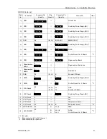
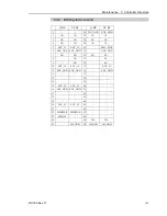
RC180 Cable List
Cable
No.
Connection
Connector Pin
Quantity
Wire
Quantity
Connector Pin
Quantity
Connection
Note
(1)
DPB
8
6
−
Noise Filter
(2)
DPB
5
3
5
Switching Power Supply (5V)
(3)
DPB
5
3
5
Switching Power Supply (24V)
(4)
DPB
5
3
5
Switching Power Supply (15V)
(5) DPB
26
26<F>
25(D-SUB)
EMERGENCY
(6)
DPB
4
4
8
Switching Power Supply (24V)
(7)
DPB
8
6
8
DMB
(8)
DPB
5
3
5
ProSix Driver Unit I/F Board
*1
(9)
DPB
5
2
5
Regeneration Board
(10)
Regeneration
Board
4
2
−
Regeneration Resistance
(11)
Regeneration
Board
3
2
−
Resistance
(12) DMB
34
34<F>
34
Encoder I/F Board
(13) DMB
4
4
4
Switching Power Supply (15V)
(14) DMB
2
2
2
ProSix Driver Unit I/F Board
*1
(15) CPU Board
50
34<F>
16<F>
34
16
DPB
Encoder I/F Board
(16) CPU Board
4
4
4
Switching Power Supply (5V)
(17) CPU Board
3
3
−
Fan
(18) CPU Board
3
3
−
Fan
(19) CPU Board
2
2
−
Temperature Sensor
(20) CPU Board
80
80<F>
80
Back Plane Board
*3
(21) M/C POWER
50
16
4,4,4,4
DMB
(22) M/C POWER
50
16
14
4,4,4,4
4,4,8
DMB
ProSix Driver Unit I/F Board
*1
<F> Flat cable
*1 When connected to ProSix Driver unit
*3 When connected to Option unit
Содержание RC180
Страница 1: ...Rev 17 EM164C3205F ROBOT CONTROLLER RC180 ...
Страница 2: ...ROBOT CONTROLLER RC180 Rev 17 ...
Страница 13: ...Safety This section contains information for safety of the Robot System ...
Страница 14: ......
Страница 19: ...Setup Operation This section contains information for setup and operation of the Robot Controller ...
Страница 20: ......
Страница 124: ...Setup Operation 12 Option Units 112 RC180 Rev 17 ...
Страница 125: ...Maintenance This section contains maintenance procedures for the Robot Controller ...
Страница 126: ...114 ...


