


Multi-Function Control ETMFC610
http://www.entecene.co.kr
295
EN
HANCED
TEC
HNOLOGY
The phase difference (ΔAngle) of the two circuits means the sum of the currently measured phase
difference(
∆𝐴𝑛𝑔𝑙𝑒
) and the compensation value
(∆𝐴𝑛𝑔𝑙𝑒
) of the phase difference
to be generated during body turn-in time by the slip frequency. The formula for calculating the
phase difference is as follows;
∆𝐴𝑛𝑔𝑙𝑒 = | ∆𝐴𝑛𝑔𝑙𝑒
+ ∆𝐴𝑛𝑔𝑙𝑒
|
= | (∠𝑉 − ∠𝑉
) + { (𝑓 − 𝑓 ) × 𝑇𝑖𝑚𝑒
× 360° } |
*. NOTE)
The variables used in the above equation are as follows.
−
∠𝑉
: Voltage phase at the source side
−
∠𝑉
: Voltage phase at the load side
−
𝑓
: Frequency at source,
𝑓
: Frequency at load, Sleep Frequency
:
𝑓
-
𝑓
−
𝑇𝑖𝑚𝑒
: CB closing time [s]
However, when the source side or load side circuit is diagonal, it is always closes regardless of
synchronous detection.
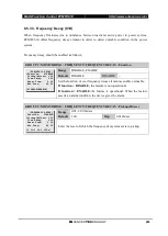
The synchronism check element in following settings should be enabled.
GROUP # / MONITORING / SYNCHRO’ CHECK / Function
Range
DISABLE, ENABLE
Default
DISABLE
Step
~
It decides whether to use synchronism check element
.
GROUP # / MONITORING / SYNCHRO’ CHECK / Max.Volt
Range
0.10~1.40 xVT
Default
1.10
Step
0.01 xVT
It sets minimum system voltage for synchronism check.
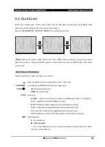
[SYNCHRO’ CHECK]
>Function: DISABLE
Max.Volt: 1.10
Min.Volt: 0.30
Max Volt Diff: 0.10
Angle Diff1: 30.0
[DISABLE,ENABLE]
[SYNCHRO’ CHECK]
Function: DISABLE
>Max.Volt: 1.10
Min.Volt: 0.30
Max Volt Diff: 0.10
Angle Diff1: 30.0
[0.10~1.40:0.01 xVT]
Содержание ETMFC610
Страница 2: ......
Страница 10: ......
Страница 110: ...Multi Function Control ETMFC610 http www entecene co kr 100 ENHANCED TECHNOLOGY Figure 7 6 Tie Algorithm ...