


IB02602004E
For more information visit: www.eaton.com
Instructional Literature
Effective: May 2008
Page
99
Instructions for the FP-6000 Protective Relay
5.4.2.11 Sync-Check
Sync-Check Settings
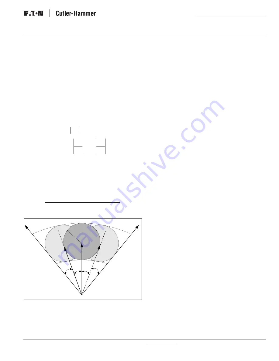
The sync-check function is provided for the applications where a
line has two-ended power sources. The sync-check function has
the abilities to check voltage magnitude and angle differences,
frequency difference (slip frequency) between the bus and the
line. The sync-check may supervise manually or automatically or
both closing operation, if enabled. This function can be
overridden by certain bus-line operation conditions and can be
bypassed with an external source. The frequency measurement
is based on the phase A on the bus side. The voltage
measurement on the line side can be any phase-to-ground or
phase-to-phase voltage. Suppose that the voltage difference
between bus and line sides at breaker closing is:
Closing breaker equivalently applies voltage sources of (-
Δ
V)
across two systems, this would disturb the systems to some
degree depending on
ζ
max Once maximum allowable
ζ
max is
determined, umax and
Δ
fmax can be determined based on
ζ
nmax.
θ
max = asin (
ζ
nmax)
Figure 22. Sync-Check Characteristic.
Sync Timeout Settings
In the version V2.01 or later application code, the setting Sync
Timeout unit is changed from cycle to second, extending Sync
Timeout limit to about 18.2 hours. Note especially that 0 timeout
means no timeout (or infinity). Depending on the value of the
Sync timeout, the sync-check logic will behave differently.
When Synch Timeout is set to zero, the sync-check function acts
like a stand alone 25 device. In this case, the sync check function
will only check two source voltages. As long as two sources meet
the in-sync and override conditions, the in-sync flag will be set.
The in-sync flag is one of the control options for use with the
Programmable Logic. Note that breaker status and a closed
breaker command have no effect on the sync checking process.
When Sync Timeout is set to non-zero, the sync-check is active
only if the breaker is open. In this case, the sync check function
will not only check two sources, but also the breaker status. The
in-sync flag will be set when two sources meet the in-sync and
override conditions with the breaker is open. The Sync failure
flag is set only if the frequency difference of two sources has
been within the range and a closing command has been
presented, but their magnitude or angle difference has been out
of their range for the specified Timeout. The Sync failure flag is
one of the control options for use with the Programmable Logic
and it inherently has no effect on the in-sync flag. The Sync
failure flag is pulsated for 300 cycles and then resets. Also, if the
breaker is closed, the Sync failure flag will be reset. Note that the
sync-check function in the case of non-zero timeout, is
independent of a closing command. A closing command is used
only to initiate the sync failure time out process. The sync failure
flag can be used to block closing breaker through an output gate.
When a closing command from either front panel or PowerNet,
or remote is received and an in-sync condition is detected, the
closing breaker flag will be set. In turn, this flag can directly
initiate a closing breaker action through an output gate.
5.4.2.12 Alarms
Protection Alarm Settings
A full set of protection alarm settings complement the protection
elements for overcurrent, over/undervoltage, unbalance and
over/underfrequency. They are designated as another protection
element, for example 50P-3, and are programmed to the alarm
output relay and alarm LED indication. The settings are similar to
the protection settings described above. These elements may be
used for alarm, tripping or logic functions. Custom programming
of the output relay is required if the desired use is not as an
alarm function.
5.4.2.13 Var Protection Settings
The reactive power protections can be used to control or monitor
the reactive power flowing through the protected device. Each
reactive power element can be configured as either forward or
reverse or both (no direction) and can operate based on either
under or over criterion. Var functions can be used for detecting
the system islanding, motor operating mode, generator field
loss, etc. The Var function can be used as a Var direction unit to
control other functions. The FP-6000 includes two Var trip units
and one alarm unit. Note that the Var threshold is in per unit,
and it is scaled based on the VT secondary rating and VT
connection to form three phase reactive power, and then is
compared against three phase total reactive power. The breaker
must be closed for these functions to be effective. When the loss
of potential block is set, undervar protections will be disabled.
The delay setting (0 to 65535 cycles in 1 cycle steps) is the time
L
B
V
V
V
$
V
$
6
B
n
V
V
$
6
,
B
L
V
V
R
BCT
cycles
power
to
f
$
5
3
2
2
max
max
P
Q
β
β
V
B
V
L
ζ
θ θ
Δ
f
>0
BCT
≠
0
Δ
f
<0
BCT
≠
0


