75
ENG
10.
Configure the
CONTROL PANEL IDENTIFICATION
for each control
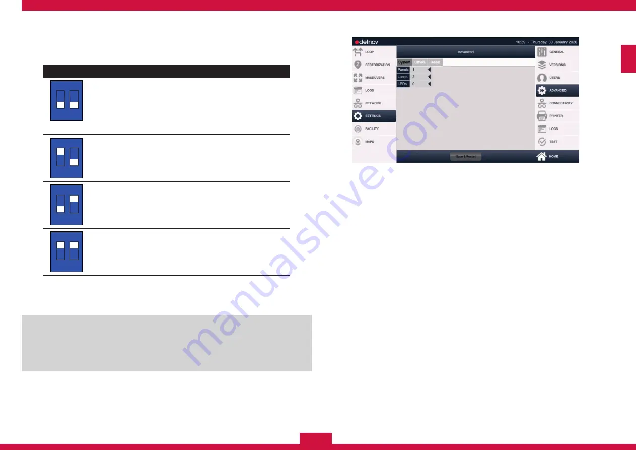
panel that forms the TOTEM by configuring SW2 correlatively from
top to bottom.
Position
SW2
1 2
Cabinet 1
The cabinet in the highest position. The control
panel will recognise the loops of this control
panel as the first of the control panel, starting
from left to right.
Default configuration of the CAB-250 control
panel
SW2
1 2
Cabinet 2
Configuration for the cabinet on the second level.
SW2
1 2
Cabinet 3
Configuration for the cabinet on the third level.
SW2
1 2
Cabinet 4
Configuration for the cabinet on the fourth level.
step 7:
Follow the installation steps from page 24 to 50, taking into
account that:
Only the SOUNDER, ALARM and FAULT outputs of the CAD-250
control panel are monitored, although it does not occupy the upper
part. For the CAB-250B or CAB-250BLED expansion cabinets,
it is not necessary to provide output wiring for the SND1, SND2,
R.FAULT and R.ALARM outputs, as they do not have any function.
8:
Once the system is started up and the parameters indicated in
this guide are configured (see section XX), configure the control
panel parameters so that the cabinets, control panel and expansion
modules are interconnected correctly and the CAD-250 can
recognise the rest of the totem control panels as expansions.
SETTINGS
(Main menu) >
ADVANCED
(Submenu)
9.
Expand the
PANELS
field and select the number of control panels
that make up the totem.
10.
Expand the
LOOPS
field and select the number of loops installed
in the totem.
11.
Activate the
BLED
switch if the control panel set includes a
CAD-250-BLED
expansion module.
Содержание CAD-250
Страница 1: ...ENG INSTALLATION GUIDE ENG ...
Страница 2: ...ENG 2 ...
Страница 3: ...3 ENG ...
Страница 17: ...17 ENG 1 3 6 3 2 4 5 ...
Страница 21: ...21 ENG 1 2 3 5 4 6 7 ...
Страница 81: ...81 ENG ...
Страница 82: ...ENG 82 ...
Страница 83: ...83 ENG ...
Страница 84: ...ENG 84 MI 375 en 2020 c CAD 250_MI_372_en_2019 d ...


