50
About Your System
–
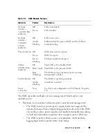
The CMC supports setting an optional enclosure Maximum Power
Limit, which either alerts or takes actions, such as throttling server
modules and/or preventing the power up of new blades to keep the
enclosure under the defined maximum power limit.
–
The CMC monitors and automatically controls cooling fans based on
actual ambient and internal temperature measurements.
–
The CMC provides comprehensive enclosure inventory and
status/error reporting.
• The CMC provides a mechanism for centralized configuration of the
following:
–
The M1000e enclosure’s network and security settings
–
Power redundancy and power ceiling settings
–
I/O switches and iDRAC network settings
–
First boot device on the server blades
–
The CMC checks I/O fabric consistency between the I/O modules and
blades and disables components if necessary to protect the system
hardware.
–
User access security.
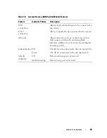
The CMC has two Ethernet ports: Gb1 is used to connect to the external
management network. The connector labeled STK ("stack") allows CMCs in
adjacent enclosures to be daisy-chained. A 24-port Ethernet switch provides
internal communication between the iDRAC on each blade, I/O modules,
optional KVM, and optional second, redundant CMC.
NOTE:
The 24-port Ethernet switch is reserved for internal communication
between the iDRAC on the blades to the CMC and the external management
network. If two CMCs are installed, the heartbeat for CMC redundancy is also
present and CMC redundancy is supported over this internal network. This internal
network is outside the data path from host LOMs and the mezzanine cards in the
blades.
At least one CMC must be installed in the primary CMC bay (see
Figure 1-22) for the system to power up. If a second, optional CMC module is
installed, failover protection and hot-plug replacement is available.
See the latest
Dell Chassis Management Controller User's Guide
at
support.dell.com/manuals
for complete instructions on how to set up and
operate the CMC module.
Содержание PowerEdge M620
Страница 1: ...Dell PowerEdge Modular Systems Hardware Owner s Manual ...
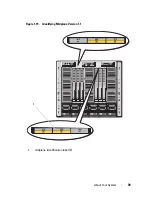
Страница 39: ...About Your System 39 Figure 1 19 Identifying Midplane Version 1 1 1 midplane identification label 2 1 ...
Страница 40: ...40 About Your System Figure 1 20 Identifying Midplane Version 1 0 1 midplane identification label 2 1 ...
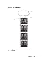
Страница 51: ...About Your System 51 Figure 1 23 CMC Daisy Chaining 1 management network 2 secondary CMC 3 primary CMC 1 2 3 ...
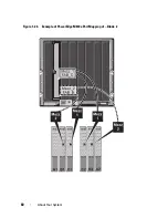
Страница 60: ...60 About Your System Figure 1 24 Example of PowerEdge M610x Port Mapping of Blade 2 ...
Страница 68: ...68 About Your System Figure 1 26 Example of Half Height Blade Port Mapping ...
Страница 136: ...136 About Your System ...
Страница 286: ...286 Installing Blade Components ...
Страница 308: ...308 Installing Enclosure Components ...
Страница 330: ...330 Running System Diagnostics ...
Страница 360: ...360 System Board Information ...
Страница 362: ...362 Getting Help ...
Страница 368: ...Index 368 V video controller installing 273 ...


