


Accelnet Plus Micro Modules User Guide
16-01687 Rev 03
Copley Controls
Page 105 of 139
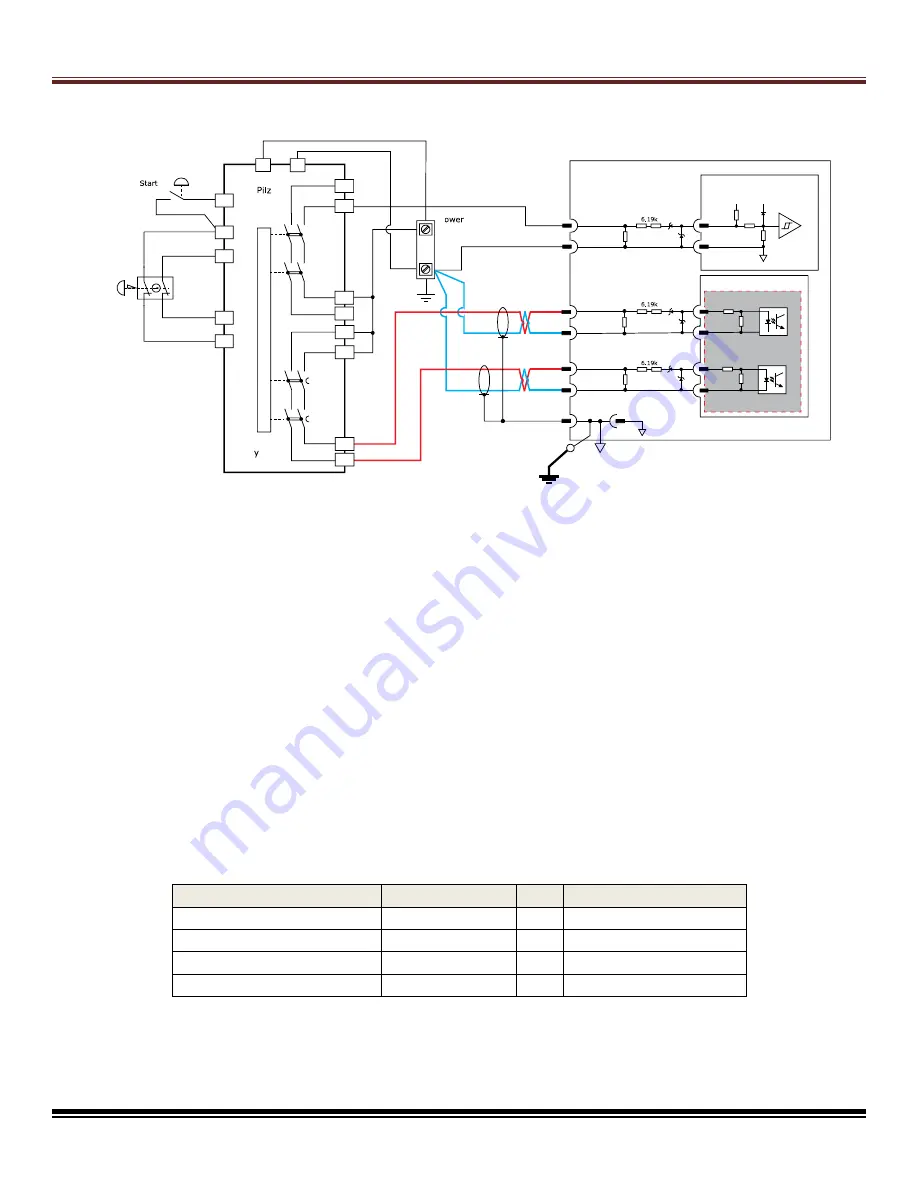
Example Wiring Diagram (SIL 3 and Cat. 3 PL e STO Implementation)
`
Emergency Stop: Stopping Category 1
The graphic above shows a wiring example for implementing a SIL 3, Cat. 3 PL e emergency
stop function using an AEV & APV drive. The example shows a safety relay with two sets of
output contacts
–
one set (K1, K2) reacts immediately to changes on the safety relay inputs
and the other (K3, K4) reacts after a user-programmable delay. A double pole, single throw
E-stop switch is used to drive two independent inputs to the safety relay.
A momentary switch is wired to the safety relay reset input and is used to reset the relay at
start-up and after an E-stop event. The enable input on the drive is wired to one of the
immediate response contacts.
The drive is programmed such that when this input is de-energized, the drive decelerates the
motor speed in a controlled fashion. After the user-programmed delay time, contacts K3 and
K4 open and de-energize the STO inputs to the drive. The drive STO function responds
accordingly and the safe state is entered within the specified drive STO response time. This
type of implementation brings the motor speed to near zero before the STO function is
activated. It is important to note that the safe state is not entered immediately upon actuation
of the E-stop button. The safe state is entered only after the STO inputs have become de-
energized and the specified STO response time has elapsed.
This table shows the components needed on the User Board as shown above:
Part
PartNum
Qty
Mfgr
Diode, zener, 6.2V, 200mW DDZ6V2BS-7
3
Diodes Inc
Diode, zener, 5.1V, 500mW DDZ5V1BSF-7
3
Diodes Inc
Resistor, 6.19 k, 0.4 W, 1% ESR10EZPF6191
6
Rohm Semiconductor
Resistor, 2.2 k, 2 W, 1%
RHC2512FT2K20
3
Stackpole Electronics
Important:
The locations of the Zener diodes for the IN1 channel are different than the locations
of the diodes for the STO-IN1 and STO-IN2 channels
.
S12
S3
6.2V
5.1V
2 AEV APV
3 AEV APV
Channel 1
Channel 2
5V
10k
1k
100 pf
5V
IN1 ENA E
STO IN1
STO IN1
STO IN2
STO IN2
INCOM
2k
2k
5.1V
6.2V
5.1V
6.2V
SGND
2k
2k
INST
D
Supply
P
2
A1
S22
S12
S3
1
2
A2
PNOZ s5
eset
E Stop
S11
S21
3
13
23
1
3
D
37
7
Safet
elay
0
2
2.2k
2.2k
2.2k
v
unctional Safety Circuit oundary


