Installation and Setup
X-320M™ User's Manual
Wiring Considerations
The analog inputs on X-320M™ are very sensitive (10 uV) and can be affected by low level noise. The
Vin- on X-320M™ should be connected to earth ground. Additionally, all cable shields should be
connected to earth ground. Users should observe single-point ground strategies, typical of
instrumentation systems.
Proper grounding may be accomplished by connecting the grounding cables to either the AC mains
ground or to the station ground.
High Output Sensors, > 5 VDC
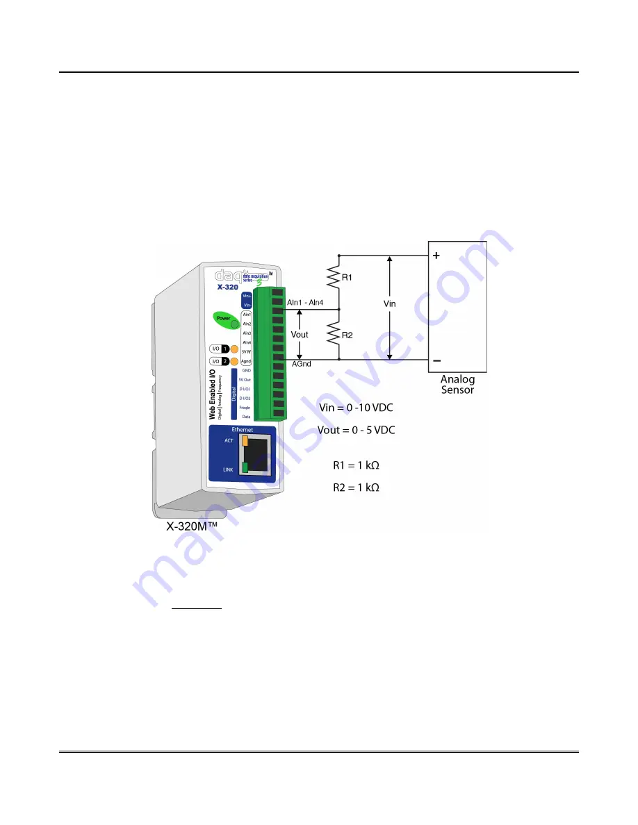
In the case of a sensor whose output levels are higher than 5 volts, a simple voltage divider can be used
to scale down the output. The following diagram shows a simple voltage divider circuit. In the example,
Vin can range from 0 to 10 volts and resistor values for R1 and R2 will be chosen so that Vout will have
a range that falls within the 0 to 5 volt range of the Analog Input.
Generally, you can choose a 1 kΩ resistor for R2 and then calculate the value of R1 using the following
formula.
Vout
=
Vin
∗(
R2
(
R1
+
R2
)
)
To determine the proper resistor value to use in the example above, use the maximum output of the
sensor (10 VDC) as Vin in the equation, the maximum input value of the the Analog Inputs (5 VDC) as
Vout, and R2 = 1 kΩ. Solving for R1 gives 1 kΩ.
R1 = 1 kΩ
R2 = 1 kΩ
As another example, if the maximum output voltage of the sensors is 15 VDC, choose R2 = 1 kΩ and by
solving the equation, R1 = 2 kΩ.
Page 20
Xytronix Research & Design, Inc.
Figure 2.2d - Voltage Divider Circuit
Содержание X-320m
Страница 1: ......


