2 Installation Manual
- 49 -
B.
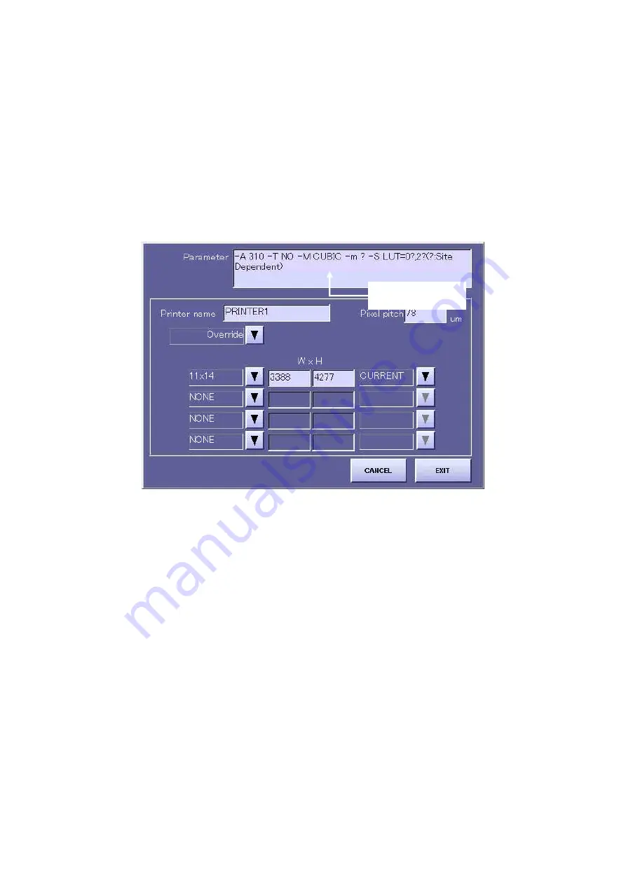
Press the “SET” button, and input the parameters of the printer to be connected based on
the pre-installation inspection details. (Refer to the separate parameter table for details
of the parameters.)
* A space must be input between each of the parameters.
By pressing the “Override” button, you can select a printer from all the registered
printers. In this case, basically you do not have to enter parameters. However, if “?” is
displayed within the parameters, you may have to enter the required parameter at the
user’s site.
[Fig 3]
Input parameters
Содержание CXDI-31
Страница 11: ...Labels and Markings Rear iii ...
Страница 14: ...Labels and Markings Rear vi ...
Страница 18: ......
Страница 20: ......
Страница 34: ...2 Installation Manual No 7 No Name E O power connector guard Name Remarks Remarks Table 3 8 ...
Страница 37: ...2 Installation Manual 4 Installation 4 1 Connecting the units 4 1 1 Connecting block diagram Fig 1 11 ...
Страница 46: ...2 Installation Manual 20 2 Set up on the left side Screw x 4 on the E O box Fig 9 Fig 10 ...
Страница 150: ...2 Installation Manual 124 8 External Dimensional Diagram 8 1 CXDI 31 8 1 1 Imaging unit Fig 1 8 1 2 E O Box Fig 2 ...
Страница 151: ...2 Installation Manual 125 8 1 3 Storage Box Fig 3 ...
Страница 152: ...2 Installation Manual 126 8 2 Option 8 2 1 Grid L 21 8mm 4 1 22 3mm 8 1 22 5mm 10 1 Fig 4 ...
Страница 157: ...3 CXDI 31 Imaging Unit 1 1 Unit Diagram Fig 1 DC DC Conversion Board ...
Страница 184: ......
Страница 186: ......
Страница 187: ...4 CXDI 31 E O Box 1 CXDI 31 E O Box Unit Diagram Fig 1 1 ...
Страница 195: ...4 CXDI 31 E O Box 2 CXDI 31 I F PCB Dip Switch SW1 Fig 5 No change SW 2 1 OFF 2 OFF 3 OFF 4 OFF Fig 6 9 ...
Страница 198: ......


