


C-1
Appendix C.
CDM Devices and CPI Bus
Campbell Scientific is introducing the CDM (Campbell Distributed Module) line
of peripherals, starting with the CDM-VW300 series of vibrating-wire analyzers.
As multiple CDM devices become available, they will be able to be networked to
communicate measurement information to a central datalogger. The
communications protocol used is the CAN (Controller Area Network) Peripheral
Interface (CPI) protocol.
CPI is a proprietary interface for communications between Campbell Scientific
dataloggers and Campbell Scientific CDM peripheral devices. It consists of a
physical layer definition and a data protocol. CDM devices are similar to
Campbell Scientific SDM devices in concept, but the use of the CPI bus enables
higher data-throughput rates and use of longer cables. CDM devices require more
power to operate in general than do SDM devices.
C.1 CDM Interconnection and Datalogger Connection
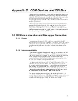
C.1.1 Power
The transmission of dc power to CDM modules is not governed by the CPI
specification but is left to the system integrator to implement. Most CDMs require
modest power from a regulated dc voltage between 11 and 32 Vdc. This power
may come from the datalogger power source or through the datalogger wiring
panel.
C.1.2 Interconnect Cable
Current Campbell Scientific dataloggers require the SC-CPI Interface to connect
with one or more CDM devices. Cat5e cable with RJ45 terminations connects a
CDM devices with the SC-CPI and other CDM devices. Cabling and connections
must be managed carefully to achieve the highest data rates and longest
transmission distances. Ideally, four twisted-pair (data, synchronization, clock,
and ground) are contained in a single shielded cable.
The data pair carries data between the SC-CPI and CDM using the CAN protocol
with ISO 11898 as the electrical standard. The CAN protocol covers device
addressing, bus arbitration, prioritization, bit-error checking, and failed-message
retransmission. The synchronization pair uses the RS-485 (TIA/EIA-485A)
electrical standard. This signal is a pulse that marks the beginning of each scan.
CDMs use this precision timing to remain synchronized, to latch, and to buffer
and transmit data to the datalogger unprompted over the data pair.
Use a pn #28558 termination resistor plug (included with the pn #29370 CPI
network kit) on the final device of a CPI chain to ensure cable communications are
working at high speeds and over very long distances. CPI pin assignments are
provided in the following figure as implemented with Cat5e cabling.
Содержание CDM-VW300 Series
Страница 2: ......
Страница 4: ......
Страница 6: ......
Страница 12: ......
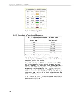
Страница 59: ...User Manual 47 Figure 7 16 LoggerNet connect screens showing frequencies from CDM VW300 ...
Страница 70: ...CDM VW300 Series Dynamic Vibrating Wire Analyzers 58 ...
Страница 76: ...Appendix B SC CPI Datalogger to CPI Interface B 4 ...
Страница 80: ...Appendix C CDM Devices and CPI Bus C 4 Figure C 2 Long cable lengths of a distributed CPI bus ...
Страница 82: ...Appendix D Digits Conversion D 2 Figure D 1 Geokon Calibration Report of a Sensor without a Thermistor ...
Страница 86: ...Appendix E Calculating Measurement Error E 4 ...
Страница 116: ...Appendix G CRBasic Program Library G 26 ...
Страница 117: ...Appendix G CRBasic Program Library G 27 ...


