


CDM-VW300 Series Dynamic Vibrating-Wire Analyzers
10
address possible problems. Do the bulk of the integration work in a comfortable
and dry location that has a communications link with Campbell Scientific during
regular business hours. If you are experienced with field deployments, set aside at
least a full day for pre-configuration work. Otherwise, set aside three to seven
days for system development before travelling to the field.
6.1
Laboratory-Mode Installation
IMPORTANT — Do not connect the CDM-VW300 analyzer or SC-CPI interface
to a PC until AFTER installing
DVWTool
1.0 or later or
DevConfig
2.04 or later.
Consult Section 7.1.1,
Software and Driver Installation,
for more information.
Laboratory mode allows for easy examination and validation of measurements.
To ensure a successful field deployment, perform this procedure before stepping
through the field-mode installation procedure of Section 6.2,
Field-Mode
Installation
.
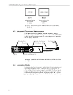
As illustrated in the following figure, a connection is made directly between the
CDM-VW300 and a PC via USB cable. No datalogger is required.
DVWTool
support software is used to configure, communicate with, and obtain sensor
readings from the CDM-VW300.
Figure 6-1. Laboratory-mode measurement system
6.1.1
Laboratory-Mode Installation Equipment
The following equipment is used in a laboratory-mode installation:
Vibrating-wire sensors
CDM-VW300 measurement module
PC
DVWTool
software
6.1.2
Laboratory-Mode Installation Procedure
The following procedure sets up the measurement system in laboratory mode:
1.
Install
DVWTool
software on the PC. Do this before connecting the CDM-
VW300 to the PC.
DVWTool
installation automatically installs drivers for the
CDM-VW300 USB connection.
Reference Section 7.1.1,
Software and Driver Installation
.
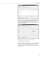
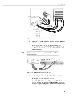
2.
Connect 12 Vdc power to the CDM-VW300 as shown in Figure 6-2.
Содержание CDM-VW300 Series
Страница 2: ......
Страница 4: ......
Страница 6: ......
Страница 12: ......
Страница 59: ...User Manual 47 Figure 7 16 LoggerNet connect screens showing frequencies from CDM VW300 ...
Страница 70: ...CDM VW300 Series Dynamic Vibrating Wire Analyzers 58 ...
Страница 76: ...Appendix B SC CPI Datalogger to CPI Interface B 4 ...
Страница 80: ...Appendix C CDM Devices and CPI Bus C 4 Figure C 2 Long cable lengths of a distributed CPI bus ...
Страница 82: ...Appendix D Digits Conversion D 2 Figure D 1 Geokon Calibration Report of a Sensor without a Thermistor ...
Страница 86: ...Appendix E Calculating Measurement Error E 4 ...
Страница 116: ...Appendix G CRBasic Program Library G 26 ...
Страница 117: ...Appendix G CRBasic Program Library G 27 ...


