


User Manual
35
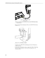
Figure 7-4. USB port on the CDM-VW300
When the connection is made,
DVWTool or DevConfig
can be used to
communicate with and configure the analyzer.
DVWTool
is the preferred software
tool.
7.7.2
CDM-VW300 to Sensor Connection
Typical single-coil vibrating-wire sensors come with either three- or five-wire
connection leads. Refer to the specifications of a particular sensor to understand
the function of each lead.
Figure 7-5. Three-wire vibrating-wire sensor leads
As illustrated in Figure 7-5 and Figure 7-6, in the three-wire configuration, two
wires are provided as connections to the coil circuit of the sensor. The third wire
is a shield wire to be connected to ground. Most vibrating-wire sensors operate
equally well with either polarity position of the two signal wires. Two coil
connections (
C
) are provided on each channel on the CDM-VW300 to which these
leads are connected.
Содержание CDM-VW300 Series
Страница 2: ......
Страница 4: ......
Страница 6: ......
Страница 12: ......
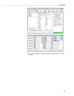
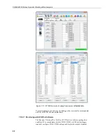
Страница 59: ...User Manual 47 Figure 7 16 LoggerNet connect screens showing frequencies from CDM VW300 ...
Страница 70: ...CDM VW300 Series Dynamic Vibrating Wire Analyzers 58 ...
Страница 76: ...Appendix B SC CPI Datalogger to CPI Interface B 4 ...
Страница 80: ...Appendix C CDM Devices and CPI Bus C 4 Figure C 2 Long cable lengths of a distributed CPI bus ...
Страница 82: ...Appendix D Digits Conversion D 2 Figure D 1 Geokon Calibration Report of a Sensor without a Thermistor ...
Страница 86: ...Appendix E Calculating Measurement Error E 4 ...
Страница 116: ...Appendix G CRBasic Program Library G 26 ...
Страница 117: ...Appendix G CRBasic Program Library G 27 ...


