


User Manual
41
7.7.5
Earth Ground Connections
Earth grounding provides protection from static discharge, transients, and power
surges. Ground lugs are provided on the CDM-VW300 and the datalogger for
connection to earth ground with high-gauge wire. Minimum 14 AWG ground
wire is recommended. The earth side of the connection should be to a grounding
rod or other grounded device. Consult the datalogger manual for more
information on earth grounding.
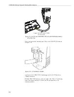
Figure 7-14. Earth ground connections
7.7.6
Communication Connections
A CDM-VW300 analyzer can connect to both PC software via USB (
DVWTool
or
DevConfig
) and the datalogger (through the SC-CPI, via RJ-45) simultaneously.
When connecting to a CDM-VW300 analyzer that is active via CPI in this way,
the device settings are locked. The settings shown in
DVWTool
will reflect the
settings that were configured on the device by the datalogger CRBasic program
using the
CDM_VW300Config()
instruction. Even if the interface of the
DVWTool
software appears to make a change to one of these locked settings, it
will not be executed at the hardware level, so it will have no impact on the
operation of the device.
7.7.6.1
SC-CPI to CPI Bus Connection
See Appendix B,
SC-CPI Datalogger to CPI Interface
.
7.7.6.2
Datalogger to SC-CPI Connection
CR3000, CR1000, and CR800 dataloggers require a SC-CPI interface to connect
with the CDM-VW300. Connect
12V
,
G
,
C1
,
C2
and
C3
from the SC-CPI to the
corresponding
12V
,
G
,
C1
,
C2
,
C3
ports of the datalogger, as shown in Figure
7-15.
Содержание CDM-VW300 Series
Страница 2: ......
Страница 4: ......
Страница 6: ......
Страница 12: ......
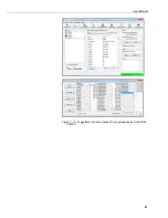
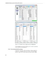
Страница 59: ...User Manual 47 Figure 7 16 LoggerNet connect screens showing frequencies from CDM VW300 ...
Страница 70: ...CDM VW300 Series Dynamic Vibrating Wire Analyzers 58 ...
Страница 76: ...Appendix B SC CPI Datalogger to CPI Interface B 4 ...
Страница 80: ...Appendix C CDM Devices and CPI Bus C 4 Figure C 2 Long cable lengths of a distributed CPI bus ...
Страница 82: ...Appendix D Digits Conversion D 2 Figure D 1 Geokon Calibration Report of a Sensor without a Thermistor ...
Страница 86: ...Appendix E Calculating Measurement Error E 4 ...
Страница 116: ...Appendix G CRBasic Program Library G 26 ...
Страница 117: ...Appendix G CRBasic Program Library G 27 ...


