


User Manual
49
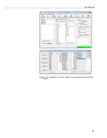
sensors. The output data can be graphed on a line graph or in a rainflow
histogram. For more information, refer to Section 7.1.2,
Using DVWTool
.
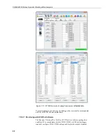
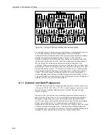
7.12.2.1.1
Fault Detection
Fault indication are shown in Figure 7-18,
Dynamic Vibrating-Wire Tool Box
Fault Indicators
. A value other than
0x00
in the
DVWTool
Diagnostic Bits
field
indicates a fault. The fault is emphasized by measurement results appearing in red
type, as illustrated in the following figure. Occasionally, the display of the
measurement values will also be flashing. A fault is accompanied by an
information icon (
i
inside a blue circle) in the
Diagnotic Bits
field. Click on the
i
to view a short decription of the fault. An argument input error is indicted by a
red field and a
!
inside a yellow triangle. Click on the
!
to view a short description
of the error.
When the frequency of a sensor changes quickly (corresponding to rapid changes
of the phenomenon under test), the energy in the vibrating wire may drop briefly
until the excitation mechanism can insert energy at the new frequency. The result
is that a low-amplitude diagnostic condition may appear for a short time. This is
expected behavior. Low- and high-amplitude diagnostic codes that appear briefly
are usually no cause for concern. For these instances, there is no loss of fidelity in
the values measured by the analyzer. However, low- and high-amplitude
diagnostic codes that occur for long continuous periods require investigation.
See Section 8.5,
Diagnostic Outputs
, for more detail about the faults that are
displayed in the
Diagnostic Bits
field.
Figure 7-18. Dynamic Vibrating-Wire Tool Box Fault Indicators
8.
Troubleshooting
CDM-VW300 series analyzers are designed to give years of trouble-free service
with reasonable care. However, if factory repair is needed, you must first contact
a Campbell Scientific application engineer to obtain an RMA (Return Materials
Authorization) number. See the
Assistance
statement at the beginning of this
manual for more information.
If the procedures in Section 6,
Installation
, do not lead to successful
measurements, review the following suggestions. If these suggestions do not
Содержание CDM-VW300 Series
Страница 2: ......
Страница 4: ......
Страница 6: ......
Страница 12: ......
Страница 59: ...User Manual 47 Figure 7 16 LoggerNet connect screens showing frequencies from CDM VW300 ...
Страница 70: ...CDM VW300 Series Dynamic Vibrating Wire Analyzers 58 ...
Страница 76: ...Appendix B SC CPI Datalogger to CPI Interface B 4 ...
Страница 80: ...Appendix C CDM Devices and CPI Bus C 4 Figure C 2 Long cable lengths of a distributed CPI bus ...
Страница 82: ...Appendix D Digits Conversion D 2 Figure D 1 Geokon Calibration Report of a Sensor without a Thermistor ...
Страница 86: ...Appendix E Calculating Measurement Error E 4 ...
Страница 116: ...Appendix G CRBasic Program Library G 26 ...
Страница 117: ...Appendix G CRBasic Program Library G 27 ...


