


User Manual
19
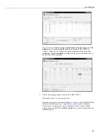
Figure 6-8. CPI communications links
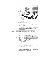
a.
Connect the SC-CPI to the datalogger. Reference Figure 6-9,
Datalogger
to SC-CPI Connection
.
CR3000, CR1000, and CR800 dataloggers require that a SC-CPI
interface the datalogger to the CDM-VW300. Connect
12V
,
G
,
C1
,
C2
,
and
C3
from the SC-CPI to the corresponding
12V
,
G
,
C1
,
C2
, and
C3
ports of the datalogger.
SC-CPI module connects to terminals
C1
,
C2
,
C3
(not SDM-C1,
SDM-C2, SDM-C3).
Figure 6-9. Datalogger to SC-CPI connection
b.
As shown in Figure 6-10, connect the CDM-VW300 to the SC-CPI.
Reference Section 7.7.3,
CDM-VW300 to SC-CPI Connection
, and
Appendix B,
SC-CPI Datalogger to CPI Interface
.
Use the RJ45 CPI cable between the CPI ports of the CDM-VW300 and
the SC-CPI interface. Use the yellow tape included in the CPI Network
Kit (pn #29370) to differentiate a cable used for CPI bus communications
from cables used for Ethernet communications.
NOTE
SC-CPI to Datalogger
12V to 12V
G to G
C1 to C1
C2 to C2
C3 to C3
SC-CPI to CDM-VW300
CPI to CPI
(RJ-45 to RJ-45)
CPI Bus
Terminator
Содержание CDM-VW300 Series
Страница 2: ......
Страница 4: ......
Страница 6: ......
Страница 12: ......
Страница 59: ...User Manual 47 Figure 7 16 LoggerNet connect screens showing frequencies from CDM VW300 ...
Страница 70: ...CDM VW300 Series Dynamic Vibrating Wire Analyzers 58 ...
Страница 76: ...Appendix B SC CPI Datalogger to CPI Interface B 4 ...
Страница 80: ...Appendix C CDM Devices and CPI Bus C 4 Figure C 2 Long cable lengths of a distributed CPI bus ...
Страница 82: ...Appendix D Digits Conversion D 2 Figure D 1 Geokon Calibration Report of a Sensor without a Thermistor ...
Страница 86: ...Appendix E Calculating Measurement Error E 4 ...
Страница 116: ...Appendix G CRBasic Program Library G 26 ...
Страница 117: ...Appendix G CRBasic Program Library G 27 ...


