


User Manual
39
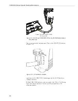
Figure 7-11. Multiple analyzers on a CPI bus
7.7.4
CDM-VW300 to Power Connection
Connect 12 Vdc power to the
Power In
connector on the side of the CDM-
VW300. Power supplies providing voltages from 9.6 to 32 Vdc, with a minimum
200 mA current rating, may be used. Connect dc power to the CDM-VW300 as
illustrated in the following figure.
SC-CPI
interface
Daisy-chained
CPI cables
Daisy-chained
power leads
CPI
terminator
Содержание CDM-VW300 Series
Страница 2: ......
Страница 4: ......
Страница 6: ......
Страница 12: ......
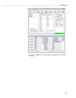
Страница 59: ...User Manual 47 Figure 7 16 LoggerNet connect screens showing frequencies from CDM VW300 ...
Страница 70: ...CDM VW300 Series Dynamic Vibrating Wire Analyzers 58 ...
Страница 76: ...Appendix B SC CPI Datalogger to CPI Interface B 4 ...
Страница 80: ...Appendix C CDM Devices and CPI Bus C 4 Figure C 2 Long cable lengths of a distributed CPI bus ...
Страница 82: ...Appendix D Digits Conversion D 2 Figure D 1 Geokon Calibration Report of a Sensor without a Thermistor ...
Страница 86: ...Appendix E Calculating Measurement Error E 4 ...
Страница 116: ...Appendix G CRBasic Program Library G 26 ...
Страница 117: ...Appendix G CRBasic Program Library G 27 ...


