


CDM-VW300 Series Dynamic Vibrating-Wire Analyzers
34
7.6.1
Frequency Considerations
In general, sensors with higher resonant-frequency ranges are more versatile when
used with a CDM-VW300 series analyzer. Higher sample rates require a higher-
frequency range on the sensor.
Based on the dynamic rate used to sample the sensor, be aware of the low-end
(minimum) frequency limitations of the CDM-VW300 as given in the following
table:
Table 7-2. Relationship of Sample Rate and Sensor Frequency
Sample
Rate (Hz)
Min Sensor
Freq (Hz)
Max Sensor
Freq (Hz)
20
290
6000
50
290
6000
100
580
6000
200
1150
6000
333.3
2300
6000
Be sure that the expected frequency response of the sensor does not fall outside
the specified limits even when responding to maximum or minimum measurement
conditions.
7.6.2
Noise Performance
See Section 5.2,
Specifications
, for more information about the noise and accuracy
of frequency readings at various sampling rates.
7.7
System Connections
IMPORTANT — Do not connect the CDM-VW300 analyzer or SC-CPI interface
to a PC until AFTER installing
DVWTool
1.0 or later or
DevConfig
2.04 or later.
Consult Section 7.1.1,
Software and Driver Installation,
for more information.
7.7.1
CDM-VW300 to PC Connection
A PC to CDM-VW300 USB connection is used in a laboratory-mode installation
and in the initial setup and troubleshooting of field-mode installations.
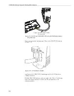
Connect a male-USB to type-micro-B male-USB cable between the PC and the
CDM-VW300 analyzer; pn #27555, provided in the CDM network kit (pn
#29370), which is shipped with each analyzer, can be used. The type-micro-B
male-USB connector connects to the CDM-VW300. The USB port is located on
the analyzer as shown in Figure 7-4,
USB port on the CDM-VW300
.
Содержание CDM-VW300 Series
Страница 2: ......
Страница 4: ......
Страница 6: ......
Страница 12: ......
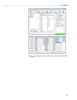
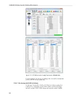
Страница 59: ...User Manual 47 Figure 7 16 LoggerNet connect screens showing frequencies from CDM VW300 ...
Страница 70: ...CDM VW300 Series Dynamic Vibrating Wire Analyzers 58 ...
Страница 76: ...Appendix B SC CPI Datalogger to CPI Interface B 4 ...
Страница 80: ...Appendix C CDM Devices and CPI Bus C 4 Figure C 2 Long cable lengths of a distributed CPI bus ...
Страница 82: ...Appendix D Digits Conversion D 2 Figure D 1 Geokon Calibration Report of a Sensor without a Thermistor ...
Страница 86: ...Appendix E Calculating Measurement Error E 4 ...
Страница 116: ...Appendix G CRBasic Program Library G 26 ...
Страница 117: ...Appendix G CRBasic Program Library G 27 ...


