


CDM-VW300 Series Dynamic Vibrating-Wire Analyzers
38
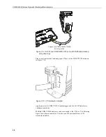
Figure 7-9. SC-CPI and CDM-VW300 CPI ports with RJ45 cable marked
with yellow tape
Place a terminator in the remaining open CPI port of the CDM-VW300 as shown
in Figure 7-10.
Figure 7-10. CPI terminator installed
Apply power to the CDM-VW300, the datalogger, and the SC-CPI interface to
confirm connectivity.
Multiple CDM-VW300 analyzers can be connected to the CPI bus. The following
figure shows these connections. The last open CPI port should have a CPI
terminator installed.
Connect SC-CPI to CDM-VW300:
RJ-45 to RJ-45
Содержание CDM-VW300 Series
Страница 2: ......
Страница 4: ......
Страница 6: ......
Страница 12: ......
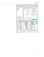
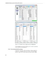
Страница 59: ...User Manual 47 Figure 7 16 LoggerNet connect screens showing frequencies from CDM VW300 ...
Страница 70: ...CDM VW300 Series Dynamic Vibrating Wire Analyzers 58 ...
Страница 76: ...Appendix B SC CPI Datalogger to CPI Interface B 4 ...
Страница 80: ...Appendix C CDM Devices and CPI Bus C 4 Figure C 2 Long cable lengths of a distributed CPI bus ...
Страница 82: ...Appendix D Digits Conversion D 2 Figure D 1 Geokon Calibration Report of a Sensor without a Thermistor ...
Страница 86: ...Appendix E Calculating Measurement Error E 4 ...
Страница 116: ...Appendix G CRBasic Program Library G 26 ...
Страница 117: ...Appendix G CRBasic Program Library G 27 ...


