


User Manual
53
or 143.04 Hz, as the
Minimum Frequency
in
DVWTool
or as the
LowFreq
argument in the
CDM_VW300Config()
CRBasic instruction.
To calculate the actual-maximum frequency, assuming a measurement is to be
taken at a scan rate of 20 Hz, use an integer multiple of 47.68 to calculate the
actual-maximum frequency. If the high-frequency limit is estimated to be 500 Hz,
enter 10 x 47.68, or 476.80 Hz, as the
Maximum Frequency
in
DVWTool
or as
the
HighFreq
argument in the
CDM_VW300Config()
CRBasic instruction.
Table 8-1. Scan Rate and Boundary Resolution
Scan Rate (Hz)
Boundary Resolution (Hz)
1
20
47.68
50
95.37
100
190.73
1
The low-frequency limit or the high-frequency limit must be an integer multiple of this frequency.
8.5.1.3
Using Diagnostic Parameters
Although a frequency reading may be provided when an amplitude or frequency
warning flag is true, the measurement should be accepted only with caution.
Rather than risk accepting bad data, consider setting the
SysOptions
argument of
the
CDM_VW300Config()
instruction to force the analyzer to report the
frequency measured under these conditions as
NAN
. A low- or high-amplitude
warning flag can be set for any one measurement, but not both. A low- or high-
frequency warning flag can be set for any one measurement, but not both. Any
one amplitude flag and any one frequency flag can be set simultaneously.
8.5.1.4
Decoding the Diagnostic Code
To recover the five diagnostic parameters from a diagnostic code, the bit pattern
represented by the twelve least-significant bits of the 32-bit diagnostic code is
decoded.
8.5.1.4.1
Excitation Strength
The eight least-significant bits (2
0
through 2
7
) of the diagnostic code represent the
excitation strength (0 to 255). When no low- or high-amplitude or frequency
warning flags are true, the diagnostic code has a value between 0 and 255. If
amplitude- or frequency-warning flags are set, the integer will be larger than 255.
To strip the warning flags out of the diagnostic code, a bit-masking operation is
performed.
The bit-masking operation uses the AND operator in CRBasic. The following
CRBasic statement decodes excitation strength in volts from the integer:
ExciteStrengthV = (DiagCode AND 255) / 42.5
where
DiagCode
is the diagnostic code and
ExciteStrengthV
is assigned a
Float
data type. This ensures that only the eight least-significant bits are considered,
resulting in an intermediate value between 0 to 255 and a result between 0 and
6 V.
8.5.1.4.2
Low-Amplitude Warning Flag
The ninth bit (2
8
or 256) corresponds to the low-amplitude warning flag. Use the
following expression to isolate the state of this bit:
Содержание CDM-VW300 Series
Страница 2: ......
Страница 4: ......
Страница 6: ......
Страница 12: ......
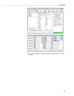
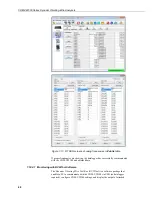
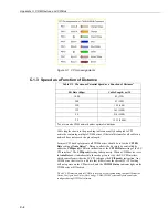
Страница 59: ...User Manual 47 Figure 7 16 LoggerNet connect screens showing frequencies from CDM VW300 ...
Страница 70: ...CDM VW300 Series Dynamic Vibrating Wire Analyzers 58 ...
Страница 76: ...Appendix B SC CPI Datalogger to CPI Interface B 4 ...
Страница 80: ...Appendix C CDM Devices and CPI Bus C 4 Figure C 2 Long cable lengths of a distributed CPI bus ...
Страница 82: ...Appendix D Digits Conversion D 2 Figure D 1 Geokon Calibration Report of a Sensor without a Thermistor ...
Страница 86: ...Appendix E Calculating Measurement Error E 4 ...
Страница 116: ...Appendix G CRBasic Program Library G 26 ...
Страница 117: ...Appendix G CRBasic Program Library G 27 ...


