


A-1
Appendix A.
Measurement Theory
A.1
Dynamic Vibrating-Wire Measurements
The key components of standard, single-coil vibrating-wire sensors are 1) a taut
wire suspended between two anchor points, and 2) an electromagnetic coil
positioned at the centre of the wire. The coil serves two functions: first as an
actuator to put energy into the wire and, second, as a pickup to detect the motion
of the wire. Static vibrating-wire measurements are typically performed in a two-
step process of exciting the wire and then measuring the wire response for a period
of time to determine its resonant frequency. The excitation waveform must be
spectrally broad, such as a swept-frequency sine wave, so as to provide sufficient
energy at the unknown resonant frequency of the wire. After the excitation, the
resonant motion of the wire is sampled, the frequency is determined, and then the
resonant energy dissipates prior to making the next measurement. The time
required for these steps typically limits this measurement method to rates slower
than 1 Hz.
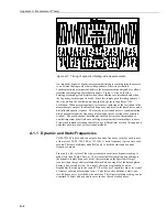
Dynamic measurements compress the measurement cycle and achieve much
higher sample rates by eliminating the broadband excitation and not allowing the
wire oscillation to decay. Figure A-1,
Timing of dynamic vibrating-wire
measurements
illustrates the timing of this process. If energy can be injected into
the oscillation at precisely the right frequency and with the correct phase, then a
very short excitation waveform with a small amplitude can maintain the resonance
of the wire. If the excitation is not phase-aligned to the wire motion, then the
resonance will be dampened rather than reinforced. In between these excitation
windows, the wire motion can be sampled and the resonant frequency determined.
Using the newly calculated frequency, the excitation is adjusted slightly as needed
to track the changes in the resonant frequency of the wire. The excitation
mechanism has very fine frequency resolution to precisely track even very subtle
changes in the resonant frequency. As can be seen in Figure A-1, there are usually
only a few oscillation cycles of the wire available for determining the wire
resonant frequency. This difficulty is overcome by the spectral analysis
algorithm, which can determine the frequency of the wire precisely, even with this
short data sample.
Содержание CDM-VW300 Series
Страница 2: ......
Страница 4: ......
Страница 6: ......
Страница 12: ......
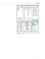
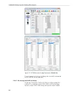
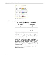
Страница 59: ...User Manual 47 Figure 7 16 LoggerNet connect screens showing frequencies from CDM VW300 ...
Страница 70: ...CDM VW300 Series Dynamic Vibrating Wire Analyzers 58 ...
Страница 76: ...Appendix B SC CPI Datalogger to CPI Interface B 4 ...
Страница 80: ...Appendix C CDM Devices and CPI Bus C 4 Figure C 2 Long cable lengths of a distributed CPI bus ...
Страница 82: ...Appendix D Digits Conversion D 2 Figure D 1 Geokon Calibration Report of a Sensor without a Thermistor ...
Страница 86: ...Appendix E Calculating Measurement Error E 4 ...
Страница 116: ...Appendix G CRBasic Program Library G 26 ...
Страница 117: ...Appendix G CRBasic Program Library G 27 ...


