


iv
G.1.3
20 Hz Measurement Example — Three CDM-VW305s, 24 Channels
............................................................................................... G-3
G.1.4
20 Hz Measurement Example — Six CDM-VW305s, 48
Channels ................................................................................ G-5
G.1.5
50 Hz Measurement Example — One CDM-VW300, Two Channels
............................................................................................... G-7
G.1.6
50 Hz Measurement Example — One CDM-VW305, Eight Channels
............................................................................................... G-9
G.1.7
50 Hz Measurement Example — Three CDM-VW305s, 24 Channels
............................................................................................. G-10
G.1.8
50 Hz Measurement Example — One CDM-VW300, Two Channels,
Rainflow Histogram ............................................................ G-11
G.1.9
50 Hz Measurement Example — One CDM-VW305, Eight Channels,
Rainflow Histogram ............................................................ G-12
G.1.10
50 Hz Diagnostic Example — One CDM-VW300, Two
Geokon 4000 Sensors with FieldCal()................................. G-14
G.1.11
50 Hz Measurement Example — One CDM-VW300, Two
Geokon 4000 Sensors with FieldCal()................................. G-16
G.1.12
50 Hz Measurement Example — One CDM-VW300, Two
Geokon 4000 Sensors with FieldCal() and CardOut() to
CF ........................................................................................ G-18
G.1.13
50 Hz Measurement Example — One CDM-VW300, Two
Geokon 4000 Sensors with FieldCal() and TableFile() to
CF ........................................................................................ G-19
G.1.14
100 Hz Measurement Example — One CDM-VW300, Two Channels
............................................................................................. G-21
G.1.15
100 Hz Measurement Example — One CDM-VW305,
Eight Channels .................................................................... G-22
G.2
Static Measurements ...................................................................... G-23
G.2.1
1 Hz Measurement Example — One CDM-VW300, Two
Channels .............................................................................. G-23
G.2.2
1 Hz Measurement Example — One CDM-VW305, Eight Channels
............................................................................................. G-24
Figures
4-1.
Two-channel CDM-VW300 wiring panel ............................................ 3
4-2.
Eight-channel CDM-VW305 wiring panel .......................................... 3
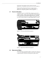
4-3.
Measurement speeds of the AVW200 and CDM-VW300 analyzers ... 4
4-4.
Single-coil vibrating-wire sensor including coil and thermistor
outputs .............................................................................................. 4
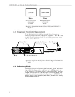
4-5.
Laboratory-mode measurement system diagram.................................. 5
4-6.
Field-mode data-acquisition system diagram ....................................... 5
6-1.
Laboratory-mode measurement system.............................................. 10
6-2.
12 Vdc power connection on the CDM-VW300 ................................ 11
6-3.
USB receptacle on CDM-VW300 and Type-Micro-B connector
of USB cable .................................................................................. 11
6-4.
Sensor connection on a CDM-VW305 ............................................... 14
6-5.
Three-wire vibrating-wire sensor connections ................................... 15
6-6.
Five-wire vibrating-wire sensor connections ..................................... 15
6-7.
Field data-acquisition system ............................................................. 17
6-8.
CPI communications links ................................................................. 19
6-9.
Datalogger to SC-CPI connection ...................................................... 19
6-10. Connecting the CPI ports of the SC-CPI and CDM-VW300 ............. 20
6-11. Install CPI bus terminator .................................................................. 20
6-12. Power connection ............................................................................... 21
6-13. Earth ground connections ................................................................... 21
7-1.
DVWTool Settings Editor and Data Display ..................................... 25
7-2.
DevConfig Settings Editor ................................................................. 27
7-3.
12 Vdc power transformer for laboratory-mode installation .............. 28
Содержание CDM-VW300 Series
Страница 2: ......
Страница 4: ......
Страница 6: ......
Страница 12: ......
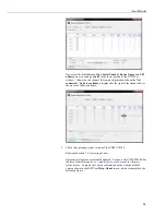
Страница 59: ...User Manual 47 Figure 7 16 LoggerNet connect screens showing frequencies from CDM VW300 ...
Страница 70: ...CDM VW300 Series Dynamic Vibrating Wire Analyzers 58 ...
Страница 76: ...Appendix B SC CPI Datalogger to CPI Interface B 4 ...
Страница 80: ...Appendix C CDM Devices and CPI Bus C 4 Figure C 2 Long cable lengths of a distributed CPI bus ...
Страница 82: ...Appendix D Digits Conversion D 2 Figure D 1 Geokon Calibration Report of a Sensor without a Thermistor ...
Страница 86: ...Appendix E Calculating Measurement Error E 4 ...
Страница 116: ...Appendix G CRBasic Program Library G 26 ...
Страница 117: ...Appendix G CRBasic Program Library G 27 ...


