


User Manual
15
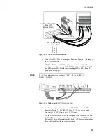
Figure 6-5. Three-wire vibrating-wire sensor connections
Figure 6-6. Five-wire vibrating-wire sensor connections
8.
Reconnect 12 Vdc power to the CDM-VW300.
9.
Confirm sensor operation.
Reference Section 7.12.1,
Sensor Validation
.
Two status LED lights are provided on the CDM-VW300 for each sensor
connection. Eight are provided on the CDM-VW305. The following table
lists LED functions and interpretations:
Table 6-1. CDM-VW300 Status LED States
Green or red flash at three-second
interval
Channel is activated.
Green flash
Response received from sensor.
Red flash
Diagnostic flags indicate there may
be a problem.
No flash, unlit
Channel is not activated.
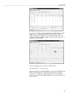
10.
Ensure that frequency readings can be obtained from the sensors.
Reference Section 7.12.2.1,
Monitoring with DVWTool Software.
Click
Connect
on the
DVWTool
window. Check the box associated with
each channel to which a sensor is connected. If all sensor systems are
operational, the
DVWTool
main window will appear much as it does in the
following figure:
Содержание CDM-VW300 Series
Страница 2: ......
Страница 4: ......
Страница 6: ......
Страница 12: ......
Страница 59: ...User Manual 47 Figure 7 16 LoggerNet connect screens showing frequencies from CDM VW300 ...
Страница 70: ...CDM VW300 Series Dynamic Vibrating Wire Analyzers 58 ...
Страница 76: ...Appendix B SC CPI Datalogger to CPI Interface B 4 ...
Страница 80: ...Appendix C CDM Devices and CPI Bus C 4 Figure C 2 Long cable lengths of a distributed CPI bus ...
Страница 82: ...Appendix D Digits Conversion D 2 Figure D 1 Geokon Calibration Report of a Sensor without a Thermistor ...
Страница 86: ...Appendix E Calculating Measurement Error E 4 ...
Страница 116: ...Appendix G CRBasic Program Library G 26 ...
Страница 117: ...Appendix G CRBasic Program Library G 27 ...


