


CDM-VW300 Series Dynamic Vibrating-Wire Analyzers
26
Resonant Amplitude (V)
sets the desired amplitude of the steady-state signal
response from the sensor.
Excitation Strength (V)
is the peak-to-peak amplitude of the excitation waveform
that is required to produce the desired response amplitude. An increase in the
Scan Rate
corresponds to a decrease in the excitation strength needed.
Diagnostic Bits
provides information on the operation of the module and can
indicate conditions during which the data may be suspect.
The
Minimum Frequency (Hz)
and
Maximum Frequency (Hz)
are the bounds
in which the resonant frequency of the sensor is expected to fall during its
operation. Signal frequencies measured outside of this range are not included in
the spectral analysis, except as noted in Section 8.5.1.1,
Description of Diagnostic
Parameters
.
Graph
button brings up a graphical display of the frequency output of the sensors.
Pressing the
Rainflow
button and selecting a channel brings up a rainflow
histogram of the frequency output of the sensor on that channel.
7.1.3
Using DevConfig
The
Device Configuration Utility
(
DevConfig
) is a software package that enables a
PC to communicate with many Campbell Scientific products. It communicates
with the CDM-VW300 via USB to configure settings and display the output of
attached sensors. No datalogger is required. Data are output to the main window
in tabular form.
Users of the CDM-VW300 should become familiar with the function and
operation of
DevConfig
. Detailed information about this software can be found in
the
DevConfig Help
system and the
LoggerNet
software manual, which is
available at
www.campbellsci.com
.
7.1.3.1
Ensure Connection is Active
The installation of
DevConfig
2.04 or later or
DVWTool
1.0 or later automatically
installs the drivers required to make a connection between the CDM-VW300 and
the PC. Do not connect a USB cable between your CDM-VW300 and the PC
until after
DevConfig
or
DVWTool
has been installed. Before starting
DevConfig
,
ensure that the CDM-VW300 analyzer is connected to the PC via USB cable.
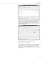
After opening
DevConfig
, choose the
CDM-VW300
port from the
Communication Port
dropdown list as indicated in Figure 7-2. Click the
Connect
button.
Содержание CDM-VW300 Series
Страница 2: ......
Страница 4: ......
Страница 6: ......
Страница 12: ......
Страница 59: ...User Manual 47 Figure 7 16 LoggerNet connect screens showing frequencies from CDM VW300 ...
Страница 70: ...CDM VW300 Series Dynamic Vibrating Wire Analyzers 58 ...
Страница 76: ...Appendix B SC CPI Datalogger to CPI Interface B 4 ...
Страница 80: ...Appendix C CDM Devices and CPI Bus C 4 Figure C 2 Long cable lengths of a distributed CPI bus ...
Страница 82: ...Appendix D Digits Conversion D 2 Figure D 1 Geokon Calibration Report of a Sensor without a Thermistor ...
Страница 86: ...Appendix E Calculating Measurement Error E 4 ...
Страница 116: ...Appendix G CRBasic Program Library G 26 ...
Страница 117: ...Appendix G CRBasic Program Library G 27 ...


