


User Manual
25
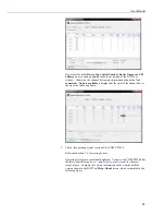
Figure 7-1. DVWTool Settings Editor and Data Display
If
CDM-VW300
does not appear in the available selections for
Com Port
, there is a problem with the installation of the device
driver or the creation of the COM port. See Section 7.1.1,
Software
and Driver Installation
, for remedial steps.
7.1.2.2
DVWTool Settings Editor
See Table 7-1,
Summary of CDM-VW300 Configuration Settings
, for a listing of
settings that can be viewed and edited with
DVWTool
.
7.1.2.3
Button and Field Descriptions
Enable —
select each checkbox to turn on the respective channel.
Dynamic Frequency
is the resonant frequency of the vibrating-wire sensor
sampled at the specified scan rate. This is the primary output of the attached
analyzer. If the
Output Format
field is set to
Freq
then this field represents the
resonant frequency of the vibrating-wire sensor. If the
Output Format
field is set
to
Freq
2
, this is the square of the resonant frequency. In either format, the
resulting number is modified by the
Multiplier
and
Offset
fields before being
output to this field.
Static Frequency
(Hz or Hz
2
)
represents the same information as the
Dynamic
Frequency
field in all respects except for the slower rate at which it is computed.
Static Thermistor (ohms)
is a measure of the resistance across the thermistor
inputs. It is measured once per second. If the
Steinhart-Hart Thermistor
Coefficients
(
A
,
B
, and
C
) are entered for the channel, then they are used to
convert the measured resistance to degrees Celsius.
Standard Deviation of Dynamic Frequency (Hz or Hz
2
)
is the standard
deviation
of the
Dynamic Frequency
field computed on one-second data. It is
output once per second. It is computed after the
Output Format
,
Multiplier
, and
Offset
have been applied.
NOTE
Содержание CDM-VW300 Series
Страница 2: ......
Страница 4: ......
Страница 6: ......
Страница 12: ......
Страница 59: ...User Manual 47 Figure 7 16 LoggerNet connect screens showing frequencies from CDM VW300 ...
Страница 70: ...CDM VW300 Series Dynamic Vibrating Wire Analyzers 58 ...
Страница 76: ...Appendix B SC CPI Datalogger to CPI Interface B 4 ...
Страница 80: ...Appendix C CDM Devices and CPI Bus C 4 Figure C 2 Long cable lengths of a distributed CPI bus ...
Страница 82: ...Appendix D Digits Conversion D 2 Figure D 1 Geokon Calibration Report of a Sensor without a Thermistor ...
Страница 86: ...Appendix E Calculating Measurement Error E 4 ...
Страница 116: ...Appendix G CRBasic Program Library G 26 ...
Страница 117: ...Appendix G CRBasic Program Library G 27 ...


