


CDM-VW300 Series Dynamic Vibrating-Wire Analyzers
32
7.5.4
Operating System Date
This field reports the release date of the CDM-VW300 operating system. This
setting is viewable only in
DevConfig
.
7.5.5
Analyzer Serial Number
This field reports the serial number of the CDM-VW300. The same serial number
is on a tag on CDM-VW300 case. This setting is viewable
DVWTool
and
DevConfig.
7.5.6
Display Rate
This setting specifies the rate at which PC displays are updated. This is not an
option in the CRBasic datalogger instruction setup.
7.5.7
Dynamic Sample Rate
This setting is entered in units of Hz (hertz) in
DVWTool
and
DevConfig
. Options
are 20, 50, 100, 200, or 333.3 kHz. This is set for lab mode using
DVWTool
. In
field mode, it is determined automatically from the
Interval
argument CRBasic
program
Scan()
instruction. It is calculated for the
Interval
parameter as:
Interval = (1 / DVWTool
Scan Rate
• 1000).
7.5.8
Device Type
This setting specifies whether the analyzer is a CDM-VW300 (Option
0
) or CDM-
VW305 (Option
1
).
7.5.9
CPI Bus Address
Each CDM-VW300 series analyzer must be given a unique address on the CPI bus
using
DVWTool
or
DevConfig
software. This address is used as the argument in
the
CPIAddress
parameter in the CRBasic program instruction
CDM_VW300Config()
. For more information about the operation of the CPI
bus, see Appendix B,
SC-CPI Datalogger to CPI Interface
. Addresses range from
1 to 120.
7.5.10
System Options
This setting determines if a numeric value or
NAN
will be stored in the datalogger
when a flag condition occurs, and whether or not the diagnostic LEDs are on or
off. This option is available for only the CRBasic datalogger program. Options
are 0, 1, 10, and 11.
7.5.11
Channels Enabled
Each channel on a CDM-VW300 series analyzer can be individually enabled for
measurement. If a channel is not enabled, the LED corresponding to it will not
flash. If the channel is enabled, but there is a diagnostic warning, the LED will
flash red. If the device is enabled and obtaining a reading properly from the
attached sensor, the LED will flash green. Channels are enabled either with check
boxes or Boolean values.
Содержание CDM-VW300 Series
Страница 2: ......
Страница 4: ......
Страница 6: ......
Страница 12: ......
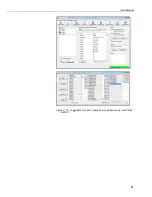
Страница 59: ...User Manual 47 Figure 7 16 LoggerNet connect screens showing frequencies from CDM VW300 ...
Страница 70: ...CDM VW300 Series Dynamic Vibrating Wire Analyzers 58 ...
Страница 76: ...Appendix B SC CPI Datalogger to CPI Interface B 4 ...
Страница 80: ...Appendix C CDM Devices and CPI Bus C 4 Figure C 2 Long cable lengths of a distributed CPI bus ...
Страница 82: ...Appendix D Digits Conversion D 2 Figure D 1 Geokon Calibration Report of a Sensor without a Thermistor ...
Страница 86: ...Appendix E Calculating Measurement Error E 4 ...
Страница 116: ...Appendix G CRBasic Program Library G 26 ...
Страница 117: ...Appendix G CRBasic Program Library G 27 ...


