


User Manual
51
response settings does not remedy the problem, force the CDM-VW300 device to
re-assess the primary frequency by a) disabling and re-enabling a channel, or b)
re-sending the CRBasic program to the datalogger.
8.5
Diagnostic Outputs
Diagnostic outputs given by CDM-VW300 series analyzers include:
Long integer diagnostic codes output at 20, 50, 100, 200 or 333.3 Hz for
each enabled channel.
Standard deviation calculated from the dynamic readings output at 1 Hz
for each enabled channel.
8.5.1
Diagnostic Codes (Dynamic)
Diagnostic codes are returned with each dynamic frequency measurement made
by the CDM-VW300 analyzer. Each diagnostic code is a 32-bit unsigned integer
encoded with five diagnostic parameters. This method of reporting diagnostics
minimizes data sent over the CPI bus, which helps to maximize measurement
throughput rates. The five diagnostic parameters are:
1.
Excitation strength
2.
Low-amplitude warning flag
3.
High-amplitude warning flag
4.
Low-frequency warning flag
5.
High-frequency warning flag
Each parameter is explained fully in Section 8.5.1.1,
Description of Diagnostic
Parameters
. The third argument of the
CDM_VW300Dynamic()
instruction
specifies the variable array to which the 32-bit diagnostic codes are written. This
array is dimensioned up to a number equal to the maximum number of channels of
the analyzer. For example, when the CDM-VW305 is measuring eight channels at
100 Hz, the diagnostic code array should be dimensioned to
(8)
. Each variable in
the array receives 100 diagnostic codes per second, or one diagnostic code for
each measurement. In total, 800 diagnostic codes are received each second.
8.5.1.1
Description of Diagnostic Parameters
Excitation strength
— reports the voltage applied by the CDM-VW300 analyzer
to keep the vibrating-wire of a sensor in motion. Excitation strength is reported as
bit values between 0 and 255, which represent excitation voltages between 0 and 6
V.
Excitation voltage is set indirectly by the user when the user enters
the
Resonant Amplitude
of the vibrating wire in
DVWTool
or the
ResonAmp
parameter of the
CDM_VW300Config()
CRBasic
instruction. The excitation level is calculated by the analyzer and
applied each time a measurement is made.
To translate the bit value to volts, divide the bit value by 42.5. For example, an
excitation bit value of 180 is equivalent to an excitation voltage of 4.235 V. To
reduce the computational load on the datalogger processor, multiply the bit value
by the reciprocal of 42.5, which is 0.02353. A multiplication operation consumes
less datalogger processor time than a division operation, which is a consideration
in fast throughput applications. Results will be substantially the same as those
obtained by a division operation.
NOTE
Содержание CDM-VW300 Series
Страница 2: ......
Страница 4: ......
Страница 6: ......
Страница 12: ......
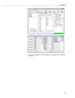
Страница 59: ...User Manual 47 Figure 7 16 LoggerNet connect screens showing frequencies from CDM VW300 ...
Страница 70: ...CDM VW300 Series Dynamic Vibrating Wire Analyzers 58 ...
Страница 76: ...Appendix B SC CPI Datalogger to CPI Interface B 4 ...
Страница 80: ...Appendix C CDM Devices and CPI Bus C 4 Figure C 2 Long cable lengths of a distributed CPI bus ...
Страница 82: ...Appendix D Digits Conversion D 2 Figure D 1 Geokon Calibration Report of a Sensor without a Thermistor ...
Страница 86: ...Appendix E Calculating Measurement Error E 4 ...
Страница 116: ...Appendix G CRBasic Program Library G 26 ...
Страница 117: ...Appendix G CRBasic Program Library G 27 ...


