20
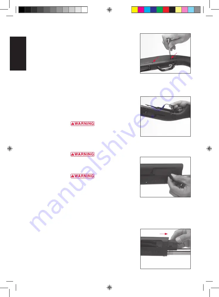
trigger group pins through the receiver. Pull on them from the
opposite side to remove them.
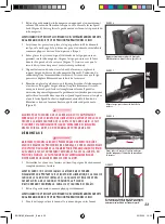
3 Grasp the trigger guard and pull it up and out of the receiver
(Figure 28).
4 Perform any cleaning of the parts and receiver cavity as necessary.
We suggest cleaning the trigger group with a quality aerosol gun
solvent. Allow it to dry and then very lightly oil the moving parts.
NOTICE!
do not disasseMble the trigger grouP beyond
this Point.
r e i n s tA l l At i o n o F t h e t r i G G e r G r o u p
1 Make sure the bolt is in the forward position.
2 Insert the trigger group into the receiver. Align the holes in the
trigger group with the holes on each side of the receiver.
3 Reinsert the trigger guard pins and gently tap them into place
with a plastic or wooden mallet, again using caution not to
scratch the receiver.
r e m o v A l o F t h e b o l t A s s e m b lY
beFore reMoving the bolt asseMbly, Place the ˝saFety” in the on
saFe Position. oPen the action and MaKe certain your shotgun
is coMPletely unloaded. KeeP the MuZZle Pointed in a saFe
direction. Failure to Follow these warnings could result in
serious injury or death.
wear eye Protection when disasseMbling and cleaning your
shotgun to Prevent sPrings, sPring-loaded Parts, solvents or
other agents FroM contacting your eyes, resulting in injury.
KeeP all aMMunition away FroM the cleaning area. never
test the Mechanical Function oF your shotgun with live
aMMunition. Failure to Follow these warnings could result
in serious injury or death.
1 Remove the barrel, gas piston, piston sleeve and piston sleeve
spring as explained previously.
2 Prior to removing the bolt assembly, it is preferred to first remove
the trigger group, as explained previously.
3 Carefully place the bolt in the forward position by holding back on
the operating handle and depressing the bolt release button.
NOTICE!
never allow the action to slaM closed by Pressing the
bolt release button without the barrel installed. iF the bolt is
released Forward with the barrel reMoved, the oPerating
handle will striKe the receiver and cause daMage.
4 Remove the operating handle by pulling the operating handle
outward (Figure 29).
5 Slide the bolt assembly forward and out of the receiver (Figure 30).
Figure 28
lift the trigger group from the receiver.
Figure 27
push the trigger group pins through
the receiver.
Figure 29
pull outward to remove the bolt handle.
Figure 30
slide the bolt forward and out of the receiver.
E
N
BRO5180_Maxus A5_v7.indd 20
02/03/10 13:30
Содержание MAXUS
Страница 6: ...4 E N BRO5180_Maxus A5_v7 indd 4 02 03 10 13 30 ...
Страница 26: ...24 E N BRO5180_Maxus A5_v7 indd 24 02 03 10 13 30 ...
Страница 27: ...25 Browning maxus Fusils semi automatiques F R BRO5180_Maxus A5_v7 indd 25 02 03 10 13 30 ...
Страница 52: ...50 F R BRO5180_Maxus A5_v7 indd 50 02 03 10 13 30 ...
Страница 53: ...51 Browning maxus HALBAUTOMATISCHE FLINTE D E BRO5180_Maxus A5_v7 indd 51 02 03 10 13 30 ...
Страница 78: ...76 D E BRO5180_Maxus A5_v7 indd 76 02 03 10 13 31 ...
Страница 79: ...77 Browning Maxus fucilE semiautomaticO I T BRO5180_Maxus A5_v7 indd 77 02 03 10 13 31 ...
Страница 104: ...102 I T BRO5180_Maxus A5_v7 indd 102 02 03 10 13 31 ...
Страница 105: ...103 Browning Maxus Escopeta SEMIautomática E S BRO5180_Maxus A5_v7 indd 103 02 03 10 13 31 ...
Страница 130: ...128 NOTES E S BRO5180_Maxus A5_v7 indd 128 02 03 10 13 31 ...


