S-7300A
6. ASSEMBLY
86
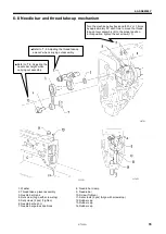
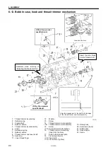
6-8. Needle bar and thread take-up mechanism
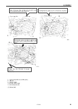
1. Washer
2. Thread take-up lever assembly
3. Needle bar crank
4. Set screw (Align with screw stop)
5. Set screws [2 pcs] (Tighten)
6. Needle bar bush U
7. Needle bar guide slide block
8. Needle bar clamp
9. Needle bar
10. Screw (Tighten)
11. Set screws [2 pcs] (Align with screw stop)
12. Rubber cap
13. Rubber cap
14. Rubber cap
1157D
■Refer to “
7-8. Adjusting the thread take-up
amount” when carrying out assembly.
■
Refer to “
7-6. Adjusting the
needle bar height” when
carrying out assembly.
1155D
1156D
Turn the machine pulley back and forth 2 or 3 times
by approximately 90° each time to move the thread
take-up lever assembly (2) to the proper position.
In this position, tighten the set screws (11).
Содержание S-7300A
Страница 8: ...S 7300A vi Control box Oil tank Transformer box 100 V 400 V system only 0874D ...
Страница 9: ...S 7300A vii ...
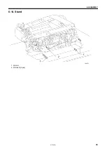
Страница 107: ...S 7300A 6 ASSEMBLY 96 1094D 6 14 Stand 1 Stand L 2 Stands R 3 pcs ...
Страница 174: ...S 7300A 8 REPLACING PARTS 163 15 Install the top cover 1 16 Install the pulley cover 2 1029D 1030D ...

