S-7300A
4. MECHANICAL DESCRIPTIONS
47
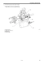
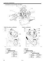
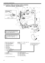
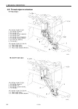
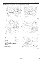
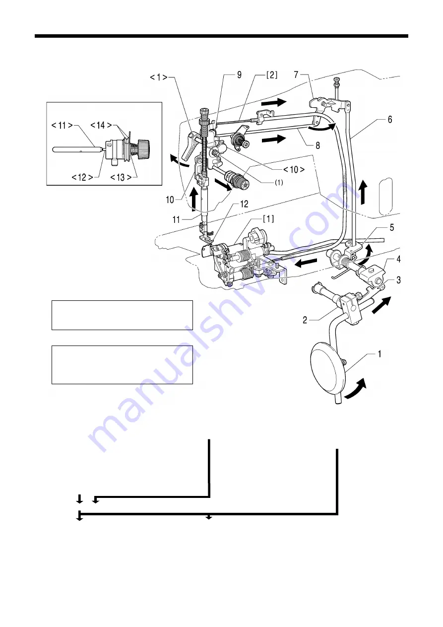
4-6. Tension release and presser foot mechanism
(Other than premier specifications)
(Presser foot is raised using the
lifting lever)
<1> Presser bar lifter lever
<10> Tension release plate
<11> Tension release stud assembly
<12> Tension release pin
<13> Tension disc presser
<14> Tension disc (Lifts up)
When the presser foot 12 is lowered, the
presser bar lifter lever spring (1)
causes the tension release plate <10> to
return.
When the thread trimming signal turns off,
parts such as the tension release wire [2]
return to their original positions.
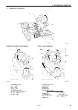
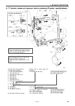
(Presser foot is raised using the
knee lifter plate assembly)
1. Knee lifter plate assembly
2. Knee lifter lever
D
3. Knee lifter connecting rod
4. Knee lifter F
5. Knee lifter R
6. Knee lifter bar
7. Knee lifter lever
D
8. Knee lifter connecting rod
9. Presser bar lifter lever
10. Lifting plate
11. Presser bar
12. Presser foot
(Raised)
(1) Presser bar lifter lever spring
(Thread trimming signal is input)
[1] Thread trimmer solenoid
[2] Tension release wire
1214D
<Other than premier
specifications>
Содержание S-7300A
Страница 8: ...S 7300A vi Control box Oil tank Transformer box 100 V 400 V system only 0874D ...
Страница 9: ...S 7300A vii ...
Страница 107: ...S 7300A 6 ASSEMBLY 96 1094D 6 14 Stand 1 Stand L 2 Stands R 3 pcs ...
Страница 174: ...S 7300A 8 REPLACING PARTS 163 15 Install the top cover 1 16 Install the pulley cover 2 1029D 1030D ...

