S-7300A
6. ASSEMBLY
93
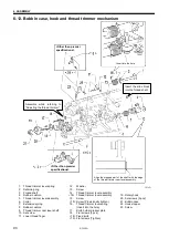
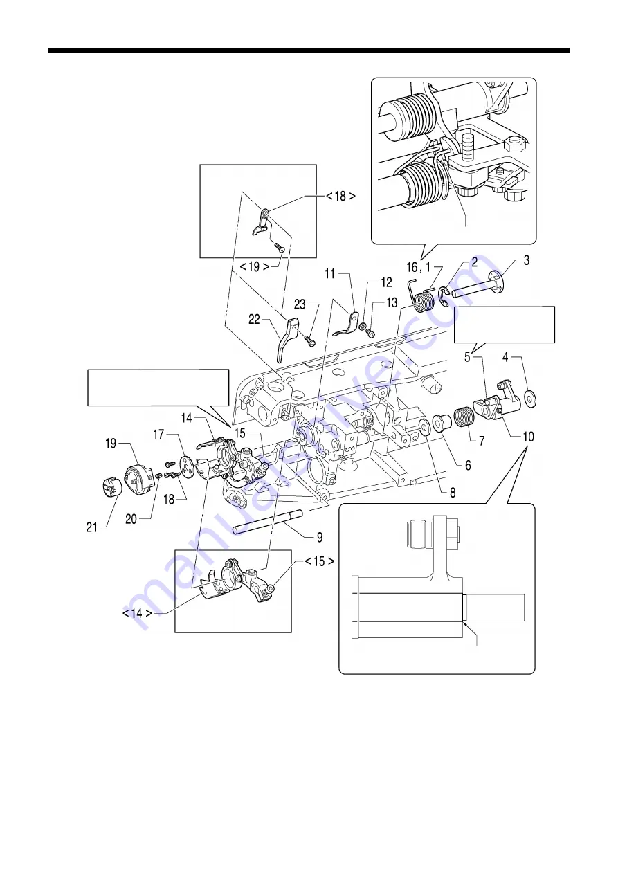
6-12. Bobbin case, hook and thread trimmer mechanism
1218D
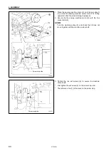
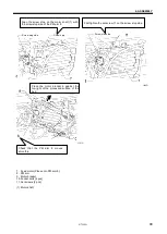
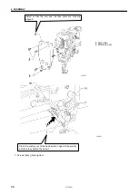
Align the stepped part of the shaft with the edge
of the thread trimmer cam lever assembly.
Insert into the hole
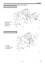
1. Thread trimmer lever spring
2. Retaining ring
3. Forked shaft
4. Rubber cushion
5. Thread trimmer lever assembly
6. Collar
7. Extension spring
8. Rubber cushion
9. Thread trimmer cam lever shaft
10. Set screw
11. Lower thread finger
12. Washer
13. Screw
14. Thread trimmer lever assembly
<14> Thread trimmer lever assembly
15. Screw
<15> Screw (Provisionally tighten)
16. Thread trimmer lever spring
(Insert into the hole)
17. Knife holder presser plate
18. Flat screws [3 pcs]
<18> Fixed knife
<19> Flat screws (Tighten)
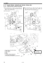
Insert the slide block
into the forked shaft.
Assemble while referring to
"Adjusting the thread trimmer".
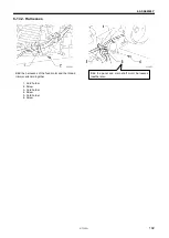
19. Rotary hook
20. Set screws [3 pcs]
21. Bobbin case
22. Hook stopper
23. Screw
<Other than premier
specifications>
<Other than premier
specifications>
Содержание S-7300A
Страница 8: ...S 7300A vi Control box Oil tank Transformer box 100 V 400 V system only 0874D ...
Страница 9: ...S 7300A vii ...
Страница 107: ...S 7300A 6 ASSEMBLY 96 1094D 6 14 Stand 1 Stand L 2 Stands R 3 pcs ...
Страница 174: ...S 7300A 8 REPLACING PARTS 163 15 Install the top cover 1 16 Install the pulley cover 2 1029D 1030D ...

