7. ADJUSTMENTS
S-7300A
133
7-10-2
.
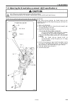
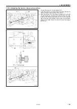
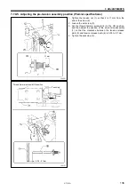
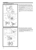
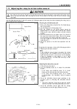
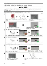
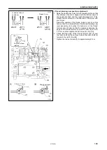
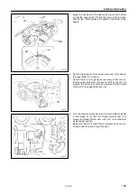
Adjusting the tension stud bracket assembly position
Tighten the tension nut (1) so that it is 5 mm (for -[][]3
specifications) or 3.5 mm (for -[][]5 specifications) from
the
end of the screw (2).
<Other than premier specifications>
1. Loosen the set screw (3).
2. Move the tension stud bracket assembly (6) forward and
back to adjust so that the tension discs (5) start to open
when the presser foot (4) rises to 4 mm above the needle
plate.
3. Tighten the set screw (3).
*
Check the vertical position of the thread take-up spring (7)
when tightening the set screw (3).
<Premier specifications>
1. Loosen the set screw (3).
2. Lower the presser foot (4).
3. Move the tension stud bracket assembly (6) forward or
back to adjust so that the thread take-up spring stopper (8)
does not protrude from the surface [A] shown in the
illustration (indent 0.6 mm or less).
4. Securely tighten the set screw (3).
1274D
1273D
<-[][]3> 5mm
<-[][]5> 3.5mm
1272D
4mm
Содержание S-7300A
Страница 8: ...S 7300A vi Control box Oil tank Transformer box 100 V 400 V system only 0874D ...
Страница 9: ...S 7300A vii ...
Страница 107: ...S 7300A 6 ASSEMBLY 96 1094D 6 14 Stand 1 Stand L 2 Stands R 3 pcs ...
Страница 174: ...S 7300A 8 REPLACING PARTS 163 15 Install the top cover 1 16 Install the pulley cover 2 1029D 1030D ...

