7. ADJUSTMENTS
S-7300A
114
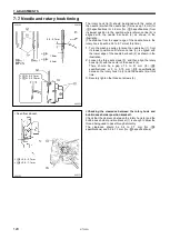
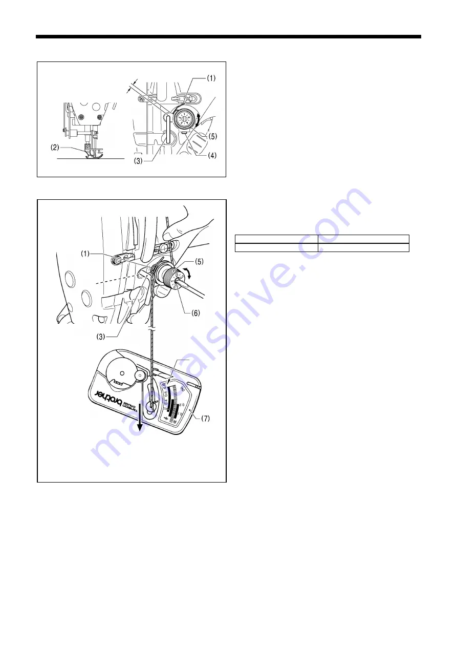
7-1. Thread tension spring
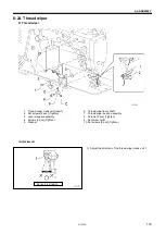
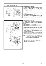
<Thread tension spring position>
The standard position of the thread take-up spring (1) is 6 to
7 mm (for -3 specifications) or 4 to 5 mm (for -5
specifications) above the surface of the arm thread guide (3)
when the presser foot (2) is lowered.
1.
Lower the presser foot (2).
2. Loosen the set screw (4).
3. Turn the thread tension bracket (5) to adjust the spring
position.
4. Securely tighten the set screw (4).
*
If the lifting lever or other method has been used to raise
the presser foot when adjusting the thread take-up spring,
the movement amount of the thread take-up spring will be
limited by the thread take-up spring stopper.
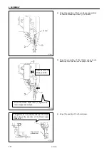
<Thread take-up spring tension>
The standard tension of the thread take-up spring (1) varies
in accordance with the machine specifications as shown in
the table.
-[][]3 specifications
0.25 - 0.35N
-[][]5 specifications
0.30 - 0.5N
1.
Press the upper thread slightly above the thread tension
bracket (5) with a finger to stop the thread spooling out.
2.
Pull the upper thread downward so that the thread take-up
spring (1) is extended to the same height as the base of
the arm thread guide (3), and then measure the tension of
the thread take-up spring (1).
3.
Insert the tip of a screwdriver into the groove in the thread
tension stud (6) and turn it to adjust the tension of the
thread tension spring (1).
NOTE:
If using a tension gauge (7) (part code: 183922-101)
to measure the tension, take the upper thread
reading from the scale [at the red line side].
*
Do not adjust the tension of the thread take-up spring if
the presser foot has been raised by the lifting lever, or if
the thread trimmer solenoid is ON.
0912D
<-[][]3> 6 - 7mm
<-[][]5> 4 - 5mm
0913D
Scale
<-[ ][ ]5>
0.3 - 0.5N
<-[ ][ ]3>
0.25 - 0.35N
Содержание S-7300A
Страница 8: ...S 7300A vi Control box Oil tank Transformer box 100 V 400 V system only 0874D ...
Страница 9: ...S 7300A vii ...
Страница 107: ...S 7300A 6 ASSEMBLY 96 1094D 6 14 Stand 1 Stand L 2 Stands R 3 pcs ...
Страница 174: ...S 7300A 8 REPLACING PARTS 163 15 Install the top cover 1 16 Install the pulley cover 2 1029D 1030D ...

