User Manual – Rev J
CS Series
California Instruments
66
4.2.7 TRANSIENT
Menu
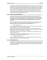
The transient menu is used to program and execute user-defined output sequences. These
output sequences are defined as a sequential list of voltage and/or current settings that can be
executed in a time controlled manner.
Each step in these lists is assigned a sequence number ranging from #0 through #99. The
numbering determines the order in which each step is executed.
Each step can control the voltage setting, voltage slew rate, frequency setting, frequency slew
rate and dwell time. The dwell time determines how long the output dwells at the current step
before progressing to the next step. Dwell times can range from 1 msec up to 900000 secs.
Transient lists can be set up from the front panel or over the bus. The transient list can be saved
with the rest of the front panel settings in one of the setup registers. (See Register Menu).
ENTRY
DESCRIPTION
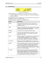
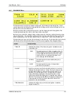
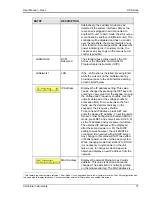
TRAN ST
Indicates the status of the transient system. Available modes
of operation are:
IDLE
Transient system is in IDLE or inactive state. To
start a transient list, press the ENTER key while
on the TRAN STATE field. Note that the output
must be ON to run a transient program or an
error message will be displayed.
WTRIG
Transient system is armed and waiting for a
trigger event.
BUSY
Transient system is active. A transient list
execution is in progress.
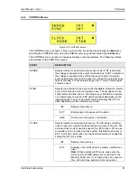
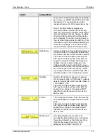
COUNT
Sets the execution count for the transient system. A count of 1
indicates the transient will run 1 times. The count value can be
set with either voltage or current knob while the cursor is on
this field. The count range is from 1 through 2E+08. Values
below 200,000 are displayed in fixed point notation. Value
higher than 200,000 are displayed as a floating point number
(2E+05). The display has insufficient characters to display the
entire mantissa so entering values above 2E+05 from the
keyboard is not recommended.
TRIG SOURCE
Indicates the trigger source for transient system. Available
trigger sources are:
Содержание 13500CS/3
Страница 5: ...User Manual Rev J CS Series California Instruments 5 SAFETY SYMBOLS ...
Страница 34: ...User Manual Rev J CS Series California Instruments 34 Figure 3 3 9000CS 2 Wiring diagram 3 Phase mode ...
Страница 35: ...User Manual Rev J CS Series California Instruments 35 Figure 3 4 13500CS 3 Wiring diagram 3 Phase mode ...
Страница 36: ...User Manual Rev J CS Series California Instruments 36 Figure 3 5 18000CS 4 Wiring diagram 3 Phase mode ...
Страница 56: ...User Manual Rev J CS Series California Instruments 56 The power source is now ready to be used ...
Страница 73: ...User Manual Rev J CS Series California Instruments 73 ...
Страница 111: ...User Manual Rev J CS Series CS Series 111 voltage rating 28 W Weight 22 Wiring AC input 30 ...

