


User Manual – Rev J
CS Series
California Instruments
33
3.5.3
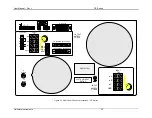
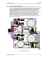
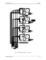
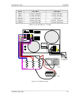
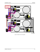
Multi-chassis Output Wiring Diagram
Figure 3-2 shows the required output connections for a 9000CS/2 two chassis system (rear-view
perspective).
Always turn off AC mains power to the 9000CS/2 by turning off the circuit
breakers on both the Master and Auxiliary 4500CS power source before making or
changing output connections.
The terminal block shown to connect the outputs of both
chassis together is provided in the 9000CS/2 ship kit. The System Interface cable is a DB25 to
DB25 M/F cable approximately 2 meters in length. (CI P/N 250778). This cable connects
between the male DB25 connector on the Master unit rear panel labeled TO AUXILIARY
INTERFACE and the female DB25 connector on the Auxiliary unit rear panel labeled TO
MASTER INTERFACE as shown in Figure 3-2. The OUTPUT SAFETY COVER must be
removed to use the System Interface and the AC Source must be installed in a cabinet with a
protective rear screen or door.
FLT INH FSTB IN1 RPV
TRIGGER
IEEE-488
AUX OUTPUT OUTPUT TB1
HI
LO
HI
LO
26VAC
5VAC
ØA
ØB
ØC
N
SENSE
ØA
ØB
ØC
N
300 VAC MAX TO
TO MASTER INTERFACE
TO AUXILIARY INTERFACE
CLOCK
LOCK
FLT INH FSTB IN1 RPV
TRIGGER
AUX OUTPUT OUTPUT TB1
HI
LO
HI
LO
26VAC
5VAC
ØA
ØB
ØC
N
SENSE
ØA
ØB
ØC
N
300 VAC MAX TO
TO MASTER INTERFACE
TO AUXILIARY INTERFACE
CLOCK
LOCK
9000CS/2
TERMINAL
BLOCK
LOAD
MASTER
AUXILIARY
A B C GND
AC SERVICE
øA
øB
øC
N
SERIAL TAG
ØA
ØB
ØC
INPUT TB3
INPUT
SAFETY
COVER
VOLTAGE INPUT
RATING
SERIAL TAG
ØA
ØB
ØC
INPUT TB3
INPUT
SAFETY
COVER
VOLTAGE INPUT
RATING
RS232C
USB
LAN
RS232C
USB
LAN
Figure 3-2: 9000CS/2 Output Wiring
Содержание 13500CS/3
Страница 5: ...User Manual Rev J CS Series California Instruments 5 SAFETY SYMBOLS ...
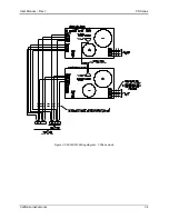
Страница 34: ...User Manual Rev J CS Series California Instruments 34 Figure 3 3 9000CS 2 Wiring diagram 3 Phase mode ...
Страница 35: ...User Manual Rev J CS Series California Instruments 35 Figure 3 4 13500CS 3 Wiring diagram 3 Phase mode ...
Страница 36: ...User Manual Rev J CS Series California Instruments 36 Figure 3 5 18000CS 4 Wiring diagram 3 Phase mode ...
Страница 56: ...User Manual Rev J CS Series California Instruments 56 The power source is now ready to be used ...
Страница 73: ...User Manual Rev J CS Series California Instruments 73 ...
Страница 111: ...User Manual Rev J CS Series CS Series 111 voltage rating 28 W Weight 22 Wiring AC input 30 ...