User Manual – Rev J
CS Series
California Instruments
99
7.4
Isolating amplifier failures in multi-box systems
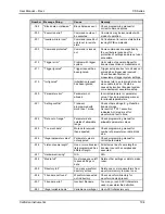
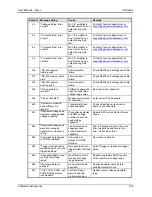
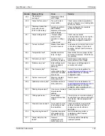
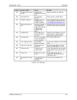
A self-test can be performed over the bus by sending the *TST? query command. The self-test
will run until the first error is encountered and terminate. The response to the query will either
be the first error encountered or 0 is no error was found. (Selftest passed).
On multi-box model configurations such as 9000CS/2, 13500CS/3 or 18000CS/4, it is possible
to isolate certain failures to a particular chassis. This can be done using the *TST? Self-test
error codes.
Note:
The self-test should always be run in 3-phase mode on all CS models. If the self-test is
run in single-phase mode, not all aspects of the Phase B and C hardware will be tested as a
result.
To execute a self-test, the IEEE-488, RS232C, LAN or USB interface must be used. The
supplied CSGui
1
Windows program command line can be used to send the *TST? Command.
The following rules apply:
1. If a current error is reported on phase øA, øB or øC, it indicates the corresponding
amplifier in the Master chassis has most likely failed.
2. If a voltage error is reported on phase øA, øB or øC, it indicates one of the auxiliary
chassis amplifiers on the phase indicated has failed. On a 2-box configuration, there is
only one auxiliary chassis. On a three or four-box configuration, it is not possible to tell
which of the two or three auxiliary amps have failed. They could also both or all have
failed in this case.
To further isolate the failed amplifier in a three or four-box configuration, the outputs of all
chassis must be disconnected from each other. Then program each phase and close the output
relay. Check the output of each chassis for the expected output current or compliance voltage.
The chassis with not output(s) will have the failed amplifier.
1
CSGui software (CI P/N 913) for Windows XP/2000 supplied on CD ROM CIC496
Содержание 13500CS/3
Страница 5: ...User Manual Rev J CS Series California Instruments 5 SAFETY SYMBOLS ...
Страница 34: ...User Manual Rev J CS Series California Instruments 34 Figure 3 3 9000CS 2 Wiring diagram 3 Phase mode ...
Страница 35: ...User Manual Rev J CS Series California Instruments 35 Figure 3 4 13500CS 3 Wiring diagram 3 Phase mode ...
Страница 36: ...User Manual Rev J CS Series California Instruments 36 Figure 3 5 18000CS 4 Wiring diagram 3 Phase mode ...
Страница 56: ...User Manual Rev J CS Series California Instruments 56 The power source is now ready to be used ...
Страница 73: ...User Manual Rev J CS Series California Instruments 73 ...
Страница 111: ...User Manual Rev J CS Series CS Series 111 voltage rating 28 W Weight 22 Wiring AC input 30 ...

