User Manual – Rev J
CS Series
California Instruments
95
3. Select this function by pressing the cursor until the arrow on the right side of the display
point to OUTP CAL. Press the ENTER key.
4. A Calibration Password (CAL PWORD) will be required. The password will be the value
of the high voltage range. For this power source the value is 135 or 270 (check
configuration limit for HIGH VOLT range limit value used). Enter this value with the Front
Panel encoder and press the ENTER key.
5. Select Phase A and enter a value of 450 (see table below) and press the ENTER key.
6. Select Phase B and enter the same value.
7. Repeat the entry for Phase C. Make sure the ENTER key is pressed each time to store
this value.
8. Connect the external current shunt and AC DVM to the Phase A output.
9. Close the output relay.
10. Set the ALC off and set the program value for the output current for Phase A to 10 amps
and 400 Hz with respect to Neut or Com. and use the adjustment indicated below to set
the output current to 10.00
±
0.10 amps.
11. Open the output relays and repeat steps 8 through 10 for phase B and C.
Output
Phase
Current Limit
Board
Adjustment Pots
OUTP CAL value
A R1 450
B R2 450
C R3 450
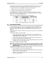
Table 6-2: Output Calibration Coefficients - Factory Defaults.
6.8
Non-Routine Distortion Adjustment
If an amplifier assembly (CI P/N 3009-411-1) has been replaced as a result of a service action, it
may be necessary to adjust the distortion setting.
The Distortion is checked with the resistive load mentioned below. The output current distortion
is an indication of the amplifier offset miss-adjustment. The Distortion Analyzer must be
connected to the current transformer for the correct indication of the distortion. A 0.01 V/amp
current transformer must be used for multi-box systems.
Note: Make this adjustment at the nominal AC line input voltage
1. Connect the Current Transformer in series with the Phase A output.
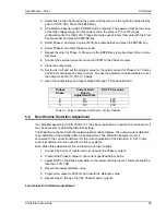
2. Program the Phase A output to the current specified below, 60Hz.
3. Adjust R105 on the Phase A amplifier to the lowest distortion level. This level should be
less than 1.0% THD.
4. Record the lowest distortion value.
5. Program the output to 2000 Hz and record the distortion value.
6. Repeat steps 1 through 3 for the Phase B and C outputs.
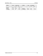
Load values for distortion adjustment:
Содержание 13500CS/3
Страница 5: ...User Manual Rev J CS Series California Instruments 5 SAFETY SYMBOLS ...
Страница 34: ...User Manual Rev J CS Series California Instruments 34 Figure 3 3 9000CS 2 Wiring diagram 3 Phase mode ...
Страница 35: ...User Manual Rev J CS Series California Instruments 35 Figure 3 4 13500CS 3 Wiring diagram 3 Phase mode ...
Страница 36: ...User Manual Rev J CS Series California Instruments 36 Figure 3 5 18000CS 4 Wiring diagram 3 Phase mode ...
Страница 56: ...User Manual Rev J CS Series California Instruments 56 The power source is now ready to be used ...
Страница 73: ...User Manual Rev J CS Series California Instruments 73 ...
Страница 111: ...User Manual Rev J CS Series CS Series 111 voltage rating 28 W Weight 22 Wiring AC input 30 ...

