User Manual – Rev J
CS Series
California Instruments
88
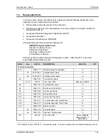
5. Principle of Operation
5.1 Overall
Description
Three-phase input power is routed from the back of the cabinet to a fuse holder terminal block
located in the bottom front of the unit. AC power is converted to a 300 VDC bus using a
switching buck converter. The DC bus is used to power all three DC/AC transconductance
current amplifiers, one for each phase. The AC input converter also generates the required DC
bias supply voltages to power the auxiliary circuits of the power source such as the
programmable controller and keyboard display.
The output of each amplifier is fed through an output transformer which steps the current down
to the required 14.80 Arms output range. The output transformers provide the required isolation
between input and output and also block any DC at the output of the power source.
The CPU controller / oscillator assembly generates the reference waveforms and provides
frequency, amplitude, and current limit control. A current and voltage sense board is located at
the top right of the unit above the transformers and is used to sense all output current and
voltage for both control and measurement purposes. The current sensor board, in conjunction
with the CPU controller, also supports the programmable RMS current limit function.
To obtain higher power levels, two to foure 4500CS (4500 VA) current sources are paralleled
together to form a 9000VA to 18000VA three-phase AC current source. This is accomplished
through the system interface, which routes the required analog and digital signals from the
4500CS master (unit with controller front panel) to the 4500CS auxiliaries.
5.2 Controller
Assembly
The Controller Assembly is located on the front panel the CS master unit. The controller
assembly consists of a single printed circuit board that plugs into the backplane motherboard.
The controller contains the main oscillator, which generates the sine wave signal setting the
frequency, amplitude and current limit level. It also senses the output voltage to provide closed
loop control of the output. The controller also handles all user interface and remote control
related tasks. The function of each of the two boards that make up the controller module is
described in the following paragraphs.
5.2.1 Programmable
Controller
This board assembly, A7, consists of the components for the CPU (DSP), generating all three
Phase waveform signals to the power amplifier and the entire program, waveform and data
memory. In addition, this board contains the circuits for all measurements. The clock and lock
circuit required to support the clock and lock mode of operation of multiple CS units is also on
this board assembly.
5.2.2
Keyboard / Display Board
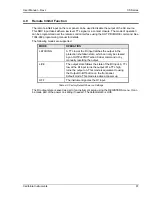
The keyboard/display assembly is assembly A9 and is mounted to the front panel. If the CS
system is used over one of the remote control interfaces, the keyboard functions can be locked
out by asserting the REMOTE state. See the CS Series Programming Manual (P/N 7004-988)
for details.
Содержание 13500CS/3
Страница 5: ...User Manual Rev J CS Series California Instruments 5 SAFETY SYMBOLS ...
Страница 34: ...User Manual Rev J CS Series California Instruments 34 Figure 3 3 9000CS 2 Wiring diagram 3 Phase mode ...
Страница 35: ...User Manual Rev J CS Series California Instruments 35 Figure 3 4 13500CS 3 Wiring diagram 3 Phase mode ...
Страница 36: ...User Manual Rev J CS Series California Instruments 36 Figure 3 5 18000CS 4 Wiring diagram 3 Phase mode ...
Страница 56: ...User Manual Rev J CS Series California Instruments 56 The power source is now ready to be used ...
Страница 73: ...User Manual Rev J CS Series California Instruments 73 ...
Страница 111: ...User Manual Rev J CS Series CS Series 111 voltage rating 28 W Weight 22 Wiring AC input 30 ...

