User Manual – Rev J
CS Series
California Instruments
65
ENTRY
DESCRIPTION
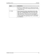
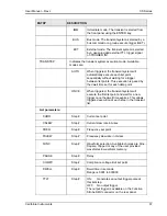
with the RMS voltage in the denominator. Note that some definitions
of THD use the fundamental component (H1) of the voltage as the
denominator.
CS units can be programmed to use the fundamental component as
the denominator. This mode can only be programmed over the bus
by sending the “MEAS:THD:MODE FUND” command. At power up
or after a reset command, the mode will revert back to RMS.
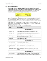
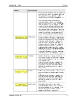
CURR THD (%A)
This readout displays the total current distortion for the selected
phase. The distortion calculation is based on the H2 through H50
with the RMS current in the denominator. Note that some definitions
of THD use the fundamental component (H1) of the current as the
denominator.
CS units can be programmed to use the fundamental component as
the denominator. This mode can only be programmed over the bus
by sending the “MEAS:THD:MODE FUND” command. At power up
or after a reset command, the mode will revert back to RMS.
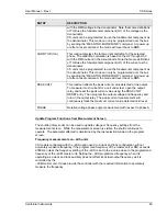
PEAK VOLT
This readout reflects the peak current value detected at the output.
To measure inrush current for a unit under test, open the output
relay and reset the peak current value using the PEAK VOLT
RESET entry. Then program the output voltage and frequency and
turn on the output relay. The peak current measurement will
continuously track the maximum current value detected until reset.
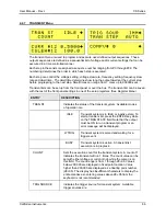
PHASE
Relative voltage phase angle measurement with respect to phase A.
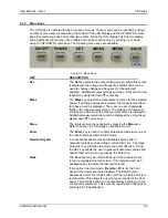
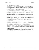
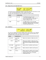
Update Program Functions from Measurement Screen
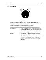
The shuttle (rotary knob) can be used to update voltage or frequency settings from the
measurement screen. While the measurement screen is visible, the shuttle continues to
operate. The parameter affected is determined by the last selection made on the program
screen.
Frequency measurements on –LKS units
CS models configured with the –LKS option used in a clock and lock configuration will not
accurately measure frequency if the programmed frequency of the master unit (-LKM) exceeds
2000 Hz unless the frequency setting of the –LKS is set to the a value close to the programmed
frequency of the –LKM master unit. Setting the –LKS programmed frequency when it is
operating as a clock and lock auxiliary does not affect its actual output frequency as it is
controlled by the
–LKM master unit. It does provide the controller with the required information to accurately
measure the frequency.
Содержание 13500CS/3
Страница 5: ...User Manual Rev J CS Series California Instruments 5 SAFETY SYMBOLS ...
Страница 34: ...User Manual Rev J CS Series California Instruments 34 Figure 3 3 9000CS 2 Wiring diagram 3 Phase mode ...
Страница 35: ...User Manual Rev J CS Series California Instruments 35 Figure 3 4 13500CS 3 Wiring diagram 3 Phase mode ...
Страница 36: ...User Manual Rev J CS Series California Instruments 36 Figure 3 5 18000CS 4 Wiring diagram 3 Phase mode ...
Страница 56: ...User Manual Rev J CS Series California Instruments 56 The power source is now ready to be used ...
Страница 73: ...User Manual Rev J CS Series California Instruments 73 ...
Страница 111: ...User Manual Rev J CS Series CS Series 111 voltage rating 28 W Weight 22 Wiring AC input 30 ...

