User Manual – Rev J
CS Series
California Instruments
92
The current measurement calibration for Phase A should be done in both single and three phase
modes as separate calibration coefficients apply to each phase mode. Voltage measurement
calibration for phase A can be done in either phase mode.
6.4
Current Measurement Calibration
Note: The Agilent HP 34401A Digital Multi meter (or higher AC accuracy DMM) must be
used for the following calibration. The DMM must be set to the AC HI ACCUR
mode for all AC measurements.
To calibrate all current measurement functions, the desired value for the measurement value of
current must be entered for each calibration coefficient. Make the indicated adjustments by
entering load current indicated by the external shunt and DVM. This should be the value
indicated by the external DVM connected to the shunt. If a 100 mOhm current shunt is used for
current, 100 mV represents 1 Amp.
Note that multi-chassis CS series will require the use of a 10 mOhm shunt, especially in single-
phase mode. Check the max power rating of the current shunt used to avoid damage to the
shunt used.
1. Connect the 100 milliohm current shunt from the Phase A Output terminal to the Neut
terminal of the power source. Connect the AC DVM to the shunt monitor terminals. All
other unused outputs must also be shorted to the Neut terminal.
2. Close the output relay. Program 11 amps, or the maximum output current of the power
system if different, and 60 Hz.
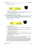
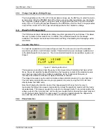
3. Go to the MEAS CAL screen. If necessary, refer to section 6.2 to get to this screen.
Press the PHASE key so only the
∅
A is indicated.
4. Move the arrow to point to MCURR FS and dial in the exact current indicated by the
external shunt and AC DVM for the Phase A output. Press the ENTER key and wait until
the new calibration coefficient is displayed.
Save this value by pressing the ENTER
key.
Repeat steps 1) through 4) for the other outputs and change the indications from A to the
respective phase to be calibrated.
6.4.1
Single and Three Phase Modes
As indicated earlier, for 3-Phase power system, repeat the preceding steps for the Phase B and
C outputs. The order in which the outputs for each phase are calibrated is not important.
Press the PHASE key to select each output to be calibrated. Monitor the output of the
respective phase by moving the HI input of the Digital Multimeter and the current shunt as
needed. The LO input should remain connected to the common LO of the sense connector.
The current measurement calibration for Phase A should be done in both single and three phase
modes as separate calibration coefficients apply to each phase mode. Voltage measurement
calibration for phase can be done in either phase mode.
6.5 Output
Calibration
The output calibration is performed automatically when the measurement calibration takes
place. As such, there is no need to perform this calibration again. The output calibration
coefficients may be viewed by selecting the OUTPUT CAL screen.
Содержание 13500CS/3
Страница 5: ...User Manual Rev J CS Series California Instruments 5 SAFETY SYMBOLS ...
Страница 34: ...User Manual Rev J CS Series California Instruments 34 Figure 3 3 9000CS 2 Wiring diagram 3 Phase mode ...
Страница 35: ...User Manual Rev J CS Series California Instruments 35 Figure 3 4 13500CS 3 Wiring diagram 3 Phase mode ...
Страница 36: ...User Manual Rev J CS Series California Instruments 36 Figure 3 5 18000CS 4 Wiring diagram 3 Phase mode ...
Страница 56: ...User Manual Rev J CS Series California Instruments 56 The power source is now ready to be used ...
Страница 73: ...User Manual Rev J CS Series California Instruments 73 ...
Страница 111: ...User Manual Rev J CS Series CS Series 111 voltage rating 28 W Weight 22 Wiring AC input 30 ...

