User Manual – Rev J
CS Series
California Instruments
78
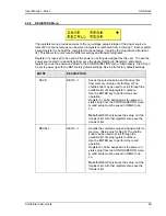
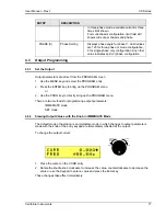
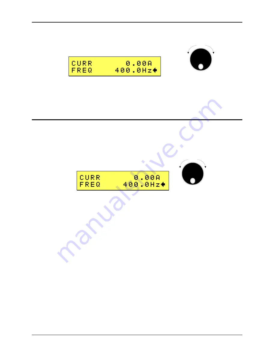
To change the output frequency:
Counter
Clock
wise
Clock
wise
INCR
DECR
1. Place the cursor on the FREQ entry
2. Rotate the shuttle
knob clockwise to increase the value, counterclockwise to decrease the
value or use the keypad to enter a value and press the Enter key.
These changes take effect immediately.
4.3.3
Change Output Values with the Knob in SET Mode
The SET mode of operation is a mode in which changes to output parameters made with the
knob or the entry keypad do not affect the output until the
Enter
key is pressed. The AC source
is put in this SET mode by pressing the
Set
key twice.
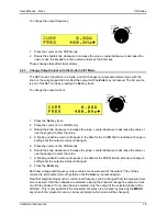
To change the output current:
Counter
Clock
wise
Clock
wise
INCR
DECR
1. Press
the
Set
key twice
2. Place the cursor on the CURR entry
3. Rotate
the
knob clockwise to increase the value, counterclockwise to decrease the value or
use the keypad to enter the value.
4. A blinking underline cursor will appear in the data for the CURR field to indicate a change in
settings but the output remains unchanged.
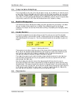
5. Place the cursor on the FREQ entry
6. Rotate the knob clockwise to increase the value, counterclockwise to decrease the value or
use the keypad to enter the value.
7. A blinking underline cursor will appear in the data for the FREQ field to indicate a change in
settings but the output remains unchanged.
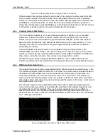
8. Press
the
Enter
key.
Both new voltage and frequency output values are now present at the output. The unit has
returned to immediate mode of operation until the
Set
key is pressed again.
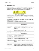
Note that output settings such as current and frequency can be changed from the measurement
screen as well. If all three phases are selected, slewing the knob will change the output current
on all three phases. If only one phase is selected, only the output of the selected phase will be
affected. This is only possible if the measurement screen is accessed by pressing the
MEAS
key while in the program menu (an arrow will prompt which value will be changed).
Содержание 13500CS/3
Страница 5: ...User Manual Rev J CS Series California Instruments 5 SAFETY SYMBOLS ...
Страница 34: ...User Manual Rev J CS Series California Instruments 34 Figure 3 3 9000CS 2 Wiring diagram 3 Phase mode ...
Страница 35: ...User Manual Rev J CS Series California Instruments 35 Figure 3 4 13500CS 3 Wiring diagram 3 Phase mode ...
Страница 36: ...User Manual Rev J CS Series California Instruments 36 Figure 3 5 18000CS 4 Wiring diagram 3 Phase mode ...
Страница 56: ...User Manual Rev J CS Series California Instruments 56 The power source is now ready to be used ...
Страница 73: ...User Manual Rev J CS Series California Instruments 73 ...
Страница 111: ...User Manual Rev J CS Series CS Series 111 voltage rating 28 W Weight 22 Wiring AC input 30 ...

